
RS-485 Best Practices: Reliable Design and Implementation
Introduction
RS-485 (TIA/EIA-485) is a widely adopted standard for industrial communication due to its robustness, long-distance capability, and multi-drop support. While RS-485 is inherently reliable, following certain best practices ensures optimal performance, noise immunity, and interoperability in real-world environments.
RS-485 is a differential signaling protocol
- Differential Pair: Data is transmitted over two wires (A and B), reducing common-mode noise.
- Multi-drop Capability: Supports up to 32 nodes (with standard loading) on a single bus and maximum up to 256 nodes with 1/8 unit loading.
- Distance: Up to 1200 meters (4000 ft) at 100 kbps, with decreasing range at higher speeds.
Cable Selection
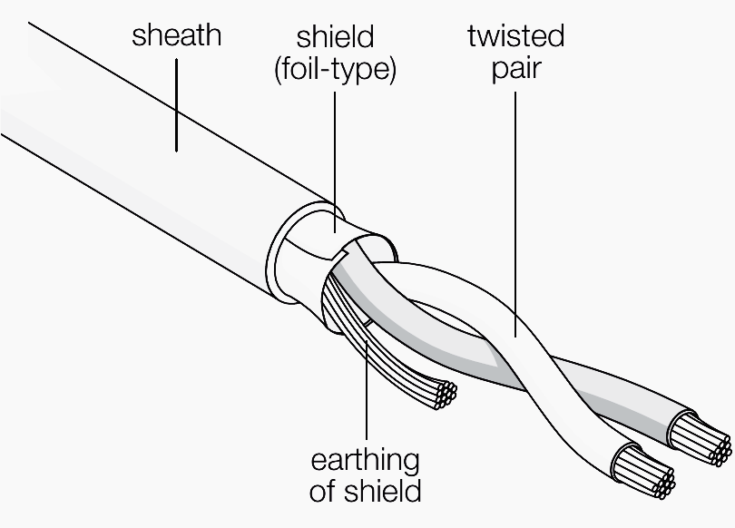
Twisted Pair and Shielded Wires
Twisted pair cables and shielded wires are two essential methods used in electrical and electronic systems to reduce electromagnetic interference (EMI) and radio frequency interference (RFI), thereby ensuring signal integrity.
- Electromagnetic Interference (EMI) is generated by switching currents, high-frequency signals, or rapidly changing voltages, especially from power lines, motors, or digital circuits.
- Radio Frequency Interference (RFI) originates from external sources like radio transmitters, mobile phones, or Wi-Fi signals.
- Both types of interference can induce unwanted noise into signal-carrying wires, disrupting data or causing signal degradation
Twisted Pair Wires
Working Principle
- When a signal travels down a wire, it produces an electromagnetic field.
- Twisting two wires together ensures they are both exposed to the same external EMI.
- Since the interference affects both wires equally (in common mode), it can be canceled out at the receiver using differential mode signaling.
Applications
- Twisted pairs are mainly effective against common mode noise.
- Common in Ethernet cables (Cat 5, Cat 6), balanced audio lines, and telecommunications
- Common Mode Noise: Identical noise on both wires (e.g., external EMI affecting both equally).
- Differential Mode Noise: Different signals or interference present on each wire (often harder to cancel).
Shielded Wires
Structure and Function
- A shielded wire consists of a signal conductor and a surrounding conductive shield (braid or foil).
- This shield acts as a barrier to EMI and RFI, either reflecting it or absorbing it and redirecting it safely to ground.
Grounding
Why Shield Must Be Grounded at Only One Point
- If grounded at multiple points, a ground loop may form due to potential differences in ground levels, allowing current to circulate through the shield and act as an antenna, introducing more noise.
- If not grounded properly, the shield may float:
- A floating shield does not provide a low-impedance path to ground.
- It can act like an antenna itself and amplify EMI/RFI instead of blocking it.
Key differences between the usage of Twisted pair and Shielded wire:
| Feature | Twisted Pair | Shielded Wire |
|---|---|---|
| Primary Protection Against | Common Mode Noise | External EMI / RFI |
| Construction | Two wires twisted together | Signal wire surrounded by a conductive shield |
| Cancellation Mechanism | Noise cancels due to symmetry | Shield reflects or grounds the noise |
| Ground Requirement | Not required for the twist itself | Must be grounded at one point only |
Network Topology
Daisy Chain Network in RS-485
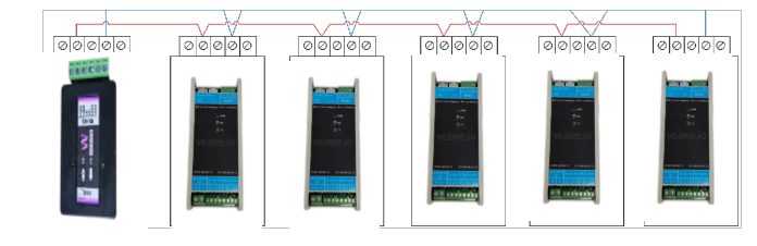
In RS-485 communication, the daisy chain (or bus) topology is the most recommended and widely used wiring configuration. In this topology, devices are connected in series—one after another along a single cable path.
- Improved Signal Integrity: Daisy chain minimizes signal reflections by maintaining proper impedance and using terminations only at the bus ends, unlike star topology which introduces signal distortion due to multiple branches.
- RS-485 Compliance: The RS-485 standard recommends daisy chain topology, ensuring better compatibility and reliability, whereas star topology often leads to communication errors.
- Efficient Cable Usage: Daisy chaining requires less cable overall, reducing installation complexity and cost compared to the longer individual cables needed in a star layout.
- Simpler Troubleshooting: The linear nature of the daisy chain makes it easier to identify and isolate faults compared to the complex branching of a star network.
- Stable Multi-Device Communication: RS-485 supports multiple nodes in a line, making daisy chaining ideal for connecting many devices with consistent performance, unlike star networks which degrade with more connections.
Termination
Signal Propagation and Impedance
In RS-485 communication, the signal travels along the twisted-pair cables as a differential voltage wave. Each signal cable has a characteristic impedance, typically around 120 ohms for twisted-pair cables. When the signal reaches the end of the cable, if it encounters a component or connection point with a different impedance, part of the signal is reflected back toward the source.
The Role of Termination Resistors
To prevent these reflections, termination resistors are placed at both ends of the RS-485 bus. These resistors match the characteristic impedance of the cable, ensuring that the signal is fully absorbed at the end of the line, rather than being reflected back. This practice is crucial for maintaining signal integrity, especially in high-speed or long-distance communication scenarios.
Placement and Value of Termination Resistors
- Placement: Termination resistors should be installed at the extreme ends of the RS-485 bus. Placing them elsewhere can lead to impedance mismatches and signal reflections.
- Value: The value of each termination resistor should match the characteristic impedance of the cable, typically 120 ohms.
Impact of Improper Termination
If termination resistors are not used or are incorrectly placed, the signal may reflect back into the transmission line which leads to :
- Signal Distortion: Reflected signals can interfere with incoming signals, causing data corruption.
- Communication Errors: Distorted signals may lead to misinterpretation of data, resulting in communication failures.
- Reduced Network Reliability: Overall system performance can degrade, especially in networks with multiple devices or long cable lengths.
Biasing
Biasing Resistors in RS-485
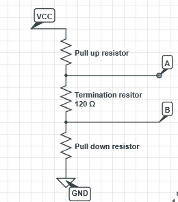
In RS-485 communication, biasing resistors (pull-up and pull-down) are used to define a known voltage level on the differential lines (A and B) when the bus is idle (no active driver transmitting).
Without biasing, the bus floats during idle time, leading to undefined voltages and false data detection.
- Pull-Up Resistor: Connected from line A to +V (usually 5V or 3.3V)
- Pull-Down Resistor: Connected from line B to GND
Purpose of Biasing Resistors
- Prevents false triggering of receivers when no data is being sent.
- Keeps the bus in a known idle state.
- Increase the driver strength effectively boosting the stability and noise immunity in noisy environment
Built-in Termination and Biasing in Master Node
- In most RS-485 systems, the master device includes built-in termination and biasing resistors to simplify wiring and ensure reliable communication.
- The termination typically consists of a 120Ω resistor between the A and B lines, which matches the cable impedance and prevents signal reflections.
- The biasing resistors (a pull-up on A and a pull-down on B) keep the bus in a known idle state, avoiding false triggers when no device is actively driving the lines.
- This setup is effective when the master is located at one end of the bus.
- Care must be taken to avoid double termination or excessive biasing, especially in larger networks.
Significance of Baud rate and Cable length
- Baud rate refers to the bits per second in RS-485.
- Higher baud rates enable faster data transmission, but:
- They reduce the maximum cable length due to increased signal degradation.
- They’re more sensitive to noise and reflections.
- Lower baud rates allow for longer communication distances and greater reliability.
Purpose of Repeaters in RS-485
- RS-485 has a limit of 32 nodes per segment and a maximum cable length (typically ~1200 meters at 9600 bps).
- Repeaters are used to:
- Extend communication distance beyond the standard cable limit.
- Increase the number of connected devices by isolating and regenerating signals between segments.
- Improve signal quality by re-amplifying degraded signals.
- Segment the network for easier fault isolation and better performance
- Simplify maintenance and scaling by modularizing the network into segments, making upgrades or repairs more manageable.
- Offer a cost-effective upgrade path for extending existing RS-485 networks without needing to transition to entirely new communication standards like Ethernet
Protocol Consideration
Modbus RTU is suitable for RS-485 because it is a simple, efficient, master-slave protocol designed for serial communication that matches RS-485’s physical characteristics: multi-drop bus topology, half-duplex operation, and long-distance transmission. It adds addressing, error checking, and message framing on top of RS-485’s robust electrical layer, enabling reliable communication in industrial environments.
If Modbus RTU (or any proper protocol) is not used on top of RS-485:
- Multiple devices may transmit simultaneously, causing data collisions on the bus.
- Without addressing, devices won’t know if incoming data is meant for them or someone else.
- Without message framing, the start and end of data messages become unclear, causing misinterpretation or mixing of data.
- Without error checking, corrupted or incomplete data may be accepted, leading to wrong or unsafe operation.
- Both sender and receiver can end up transmitting at the same time, causing signal interference and communication failure.
RS-485 typically works in half-duplex mode, meaning data can flow in only one direction at a time on the same pair of wires.
- Only one device (usually the master or the addressed slave) should transmit while others listen.
- The receiver must wait for the sender to finish transmitting before replying.
- This coordination is ensured by a protocol like Modbus RTU, which manages who talks when.
Isolation
Isolated and Non-Isolated RS-485
Galvanic isolation is used with RS-485 to ensure that while two parts of a system exchange signals or power, they have no direct electrical contact. This isolation improves safety and system robustness by breaking ground connections.
In isolated RS-485, galvanic isolation is included between the RS-485 transceiver and the system’s logic or power side. This is done using opto-isolators, transformers, or digital isolators.
Reasons for using galvanic isolation
- Ground Loop Prevention
When two devices have different ground potentials and are directly connected, ground loops can occur. These loops allow unwanted current to flow, causing noise, data errors, or damage. Galvanic isolation eliminates the electrical path, preventing such issues. - Electrical Safety
In the event of a fault or high voltage on one side of the system, galvanic isolation protects the rest of the system — especially low-voltage control or monitoring circuits — from dangerous voltage levels. - Surge Protection
Voltage surges or spikes, such as those caused by lightning or switching transients, can travel through communication lines and damage sensitive electronics. Isolation helps block these surges from propagating across the system.
Why isolation may be omitted
- Negligible Ground Potential Differences
In small systems or devices located close together, the ground potential difference between devices is minimal, so the risk of ground loops is low. - Cost Reduction
Eliminating isolators reduces component count, cost, and design complexity, making it suitable for budget-sensitive applications. - Compact Design
Fewer components allow for smaller circuit boards, which is important in embedded or consumer devices. - Simpler Power Design
Without isolation, there’s no need for isolated power supplies, simplifying the system’s power architecture. - Low-Risk Environments
In controlled environments where surge, noise, and fault risks are low, non-isolated RS-485 performs adequately.
| Feature | Isolated RS-485 | Non-Isolated RS-485 |
|---|---|---|
| Galvanic Isolation | Yes | No |
| Ground Loop Protection | Excellent | Minimal |
| Noise Immunity | High | Low to Moderate |
| Surge Protection | Yes | Limited |
| Cost & Complexity | Higher | Lower |
| Use Case | Industrial, noisy, long-distance | Simple, short-range, low-risk |
Surge Protective Devices (SPD)
A surge in RS-485 refers to a sudden high-voltage spike on the communication lines, often caused by:
- Lightning strikes
- Power line transients
- Ground potential differences
- Inductive load switching (e.g., motors)
Surges can damage transceivers, corrupt data, or even destroy devices if unprotected.
Methods to Control Surges in RS-485
- TVS (Transient Voltage Suppression) Diodes
- Fast-acting diodes that clamp high voltages to safe levels.
- Installed across RS-485 A/B lines and to ground.
- Common-Mode Chokes
- Suppress high-frequency noise and surge energy.
- Placed on differential pairs to block unwanted interference.
- Isolation (Optical or Magnetic)
- Use of isolated RS-485 transceivers to separate the communication bus from the device’s ground.
- Protects internal circuits from high surge voltages.
- Proper Grounding and Shielded Cables
- Use twisted-pair shielded cables with proper grounding to reduce induced surges.
- Avoid ground loops by maintaining a single ground reference.
- Surge Protection Devices (SPD)
- Dedicated surge protectors can be installed in-line to absorb and divert high-energy transients.
Conclusion
When designed and deployed with care, RS-485 can be a highly reliable and noise-immune communication interface, even in harsh industrial environments. Following these best practices ensures long-term performance and interoperability across devices.