Ethernet Dual RS232 Converter UC-ETH-RS...
Ethernet Dual RS232 Converter UC-ETH-RS232-D

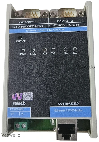
The UC-ETH-RS232-D is a dual-port industrial Ethernet to RS232 serial device server designed to connect legacy RS232 equipment to Ethernet local area networks. Featuring two independent RS232 channels (both supporting hardware flow control RTS/CTS) and an auto-sensing 10/100M RJ45 Ethernet port, it allows centralized SCADA software, PC workstations, and PLCs to access distributed serial instruments over TCP/IP networks.
Key Features
- 2 independent RS-232 serial ports with terminal block connections
- Full hardware RTS/CTS flow control on both channels
- Auto-sensing 10/100M Ethernet RJ45 port with 2 kV magnetic isolation
- Bi-directional Modbus TCP to Modbus RTU protocol gateway on both ports
- Multi-client TCP Server, TCP Client, UDP, and Httpd socket modes
- Transparent data pass-through for ASCII, CNC, and telemetry streams
- Built-in web server for browser-based configuration and diagnostics
- Configurable baud rates from 300 bps to 250 kbps per channel
- ±15 kV ESD and TVS surge protection on Ethernet, serial, and power lines
- 12V to 24V DC wide power supply input with reverse polarity protection
- 35 mm DIN rail and wall mountable housing
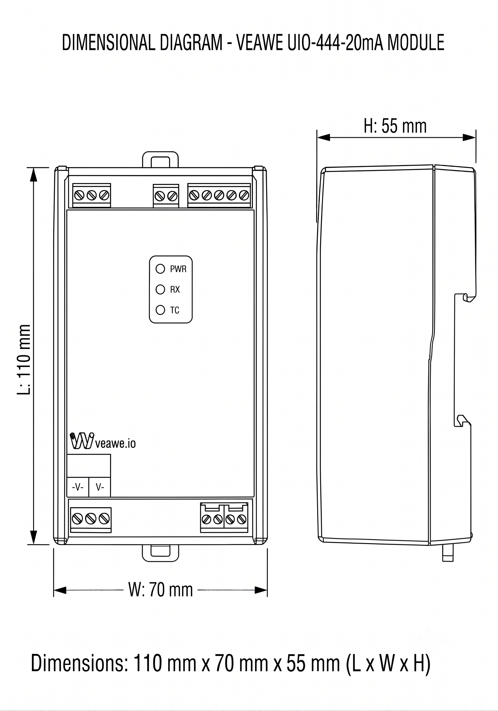
- Dimensions: 110 mm × 70 mm × 50 mm
Ordering Information
| Product Code | Description |
|---|---|
| UC-ETH-RS232-D | Ethernet Dual RS232 Converter (Dual Port, Flow Control, 12~24V DC) |
| SPD-ETH-RJ45 | Ethernet Surge Protection Device |
| UC-ETH-RS485-D | Ethernet to Dual RS485 Converter |
| UC-RS232 | USB to RS232 Converter |
| UC-ISO-232-232 | Isolated RS232 To RS232 Repeater |
Applications
- CNC Machinery & DNC Networks: Networking legacy CNC machines and shop floor controllers over plant Ethernet.
- Weighbridge & Scale Integration: Bridging weighing indicators and barcode printers directly to cloud or enterprise ERP systems.
- Access Control & Security Panels: Integrating RS232 badge readers, security controllers, and biometric panels onto IP networks.
- Substation Remote Telemetry: Remote polling and management of legacy substation relays, gensets, and UPS controllers.
Specifications
| Parameter | Value |
|---|---|
| Mounting Type | 35 mm DIN Rail & Wall Mounting |
| Dimensions | 110 mm x 74 mm x 70 mm (L x W x H) |
| Enclosure Material | Industrial ABS Plastic |
| Operating Temperature | -40 °C to +85 °C |
| Storage Temperature | -40 °C to +85 °C |
| Relative Humidity | 5% to 95% RH (non-condensing) |
Electrical Specifications
| Parameter | Specification |
|---|---|
| Power Supply | 12V ~ 24V DC (30V DC maximum limit) |
| Working Current | 200 mA Max |
| Reverse Polarity Protection | Integrated series diode on DC power input |
| Ethernet Port | 1x RJ45 10/100 Mbps auto-negotiation, auto MDI/MDIX |
| Ethernet Isolation | 2,000 V RMS built-in transformer magnetic isolation |
| Serial Ports | 2x RS232 Channels (DB9 Male connectors, both with RTS/CTS) |
| Baud Rate Range | 300 bps to 250 kbps |
| Data Format | 7/8 Data bits, 1/2 Stop bits, None/Even/Odd Parity |
| RS232 Receive Input | \(\pm 30\text{V}\) maximum tolerance (RS232-1 & RS232-2) |
| RS232 Transmit Output | \(\pm 7\text{V}\) nominal output swing (RS232-1 & RS232-2) |
Isolation & Protection Specifications
| Parameter | Value | Standard / Notes |
|---|---|---|
| Ethernet Isolation | 2,000 V RMS | Galvanic magnetic barrier across RJ45 |
| RS232 ESD Immunity | \(\pm 15\text{kV}\) Air / HBM, \(\pm 8\text{kV}\) Contact | IEC 61000-4-2 ESD protection across all RS232 pins |
| Surge Protection | Fast Transient Clamping | TVS protection for Ethernet, RS232, and power lines |
LED Indications and Diagnostics
| LED | Color | Status | Description |
|---|---|---|---|
| PWR | Red | ON | Operating power connected and regulated |
| LINK | Green | ON / Blinking | Ethernet physical link established / network activity |
| RX1 | Yellow | Blinking | RS232 Channel 1 receive data activity |
| TX1 | Green | Blinking | RS232 Channel 1 transmit data activity |
| RX2 | Yellow | Blinking | RS232 Channel 2 receive data activity |
| TX2 | Green | Blinking | RS232 Channel 2 transmit data activity |
| F-RESET | – | Push Button | Restores factory default network & serial settings |
Network & Gateway Configuration
Default Factory Settings
| Parameter | Default Value | Notes |
|---|---|---|
| IP Address | 192.168.0.7 |
Static IP (DHCP selectable in web interface) |
| Subnet Mask | 255.255.255.0 |
Class C Subnet |
| Default Gateway | 192.168.0.1 |
Default router IP |
| Web UI Port | 80 |
HTTP browser access (http://192.168.0.7) |
| Web Username / Password | admin / admin |
Default credentials |
| Channel 1 TCP Port | 23 |
Default socket port for RS232-1 |
| Channel 2 TCP Port | 26 |
Default socket port for RS232-2 |
| Default Serial Settings | 115200 bps, 8, N, 1 |
Configurable 300 bps to 250 kbps |
Operating Modes & Features
- Transparent Serial Connection: Under RS232 Settings, set Work Mode to
Nonefor transparent serial data tunneling over TCP/UDP. Suitable for custom serial protocols, ASCII terminals, Virtual COM ports, and Telnet connections. - Modbus TCP to Modbus RTU: Selectable under RS232 Settings for bridging Modbus TCP master software directly to remote Modbus RTU slave devices across both channels.
- Packet Transmission Mechanisms:
- Auto Mode (
0/0): Data packet is transmitted when 4 bytes time passes without new data (~350 \(\mu\)s @ 115200 Baud) or when buffer reaches 1,460 bytes. Recommended for most protocols. - Fixed Mode: Transmits when user-defined timeout (ms) or user-defined byte count is reached.
- Web to Serial Testing: Integrated browser tool (Channel 1) allowing operators to view received serial data and transmit ASCII or Hex strings directly from the web interface.
Mechanical Dimensions
Terminal Details & Port Pinouts
RS232 & Power Connections
| Connector / Terminal | Pin | Label | Signal | Description |
|---|---|---|---|---|
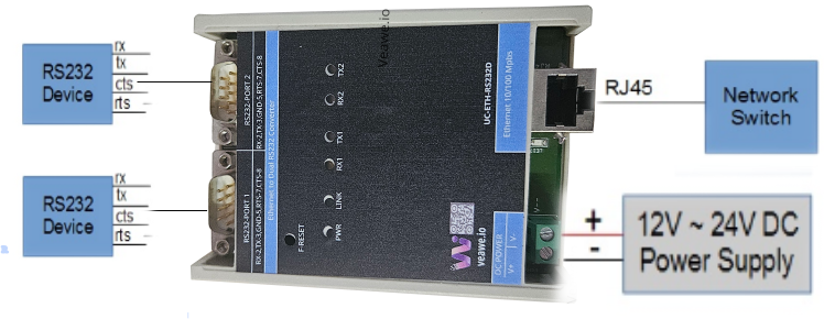
| RS232-PORT 1 | 2 | 2-RX | Input | RS232 Receive data (connects to external TX) |
| (DB9 Male) | 3 | 3-TX | Output | RS232 Transmit data (connects to external RX) |
| 5 | 5-GND | Ground | Common Signal Ground | |
| 7 | 7-RTS | Output | Request to Send flow control line | |
| 8 | 8-CTS | Input | Clear to Send flow control line | |
| RS232-PORT 2 | 2 | 2-RX | Input | RS232 Receive data (connects to external TX) |
| (DB9 Male) | 3 | 3-TX | Output | RS232 Transmit data (connects to external RX) |
| 5 | 5-GND | Ground | Common Signal Ground | |
| 7 | 7-RTS | Output | Request to Send flow control line | |
| 8 | 8-CTS | Input | Clear to Send flow control line | |
| DC POWER | 1 | V+ | Power | DC Power Supply Positive (+12V to +24V DC) |
| (Screw Terminal) | 2 | V- | Power | DC Power Supply Negative (Ground return) |
Typical Connection Diagram
Revision History
| Revision | Date | Description of Change |
|---|---|---|
| Rev 1.0 | 2026-09-09 | Initial datasheet release |
Get the latest version of this datasheet : click here..
Support
Website: www.veawe.io
Email: info@veawe.io