4AI Modbus Remote I/O Module

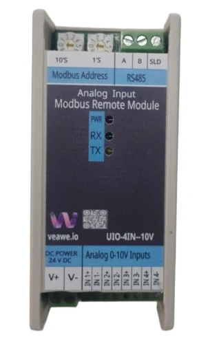
Compact Modbus RTU remote I/O module with four 0–10V analog inputs, configurable alarm logic.
Key Features
- 4 Channel 0–10V Analog Inputs
- 16-bit analog resolution
- Raw analog value resolution of 0.001V
- Sensor open / broken wire indication
- Individual channel offset and gain calibration
- Integer and IEEE754 float value support
- Modbus RTU over RS-485
- Rotary address switch for address selection from 1 to 99
- Wide Supported baud rates from 300 to 115200
- DIN rail mountable
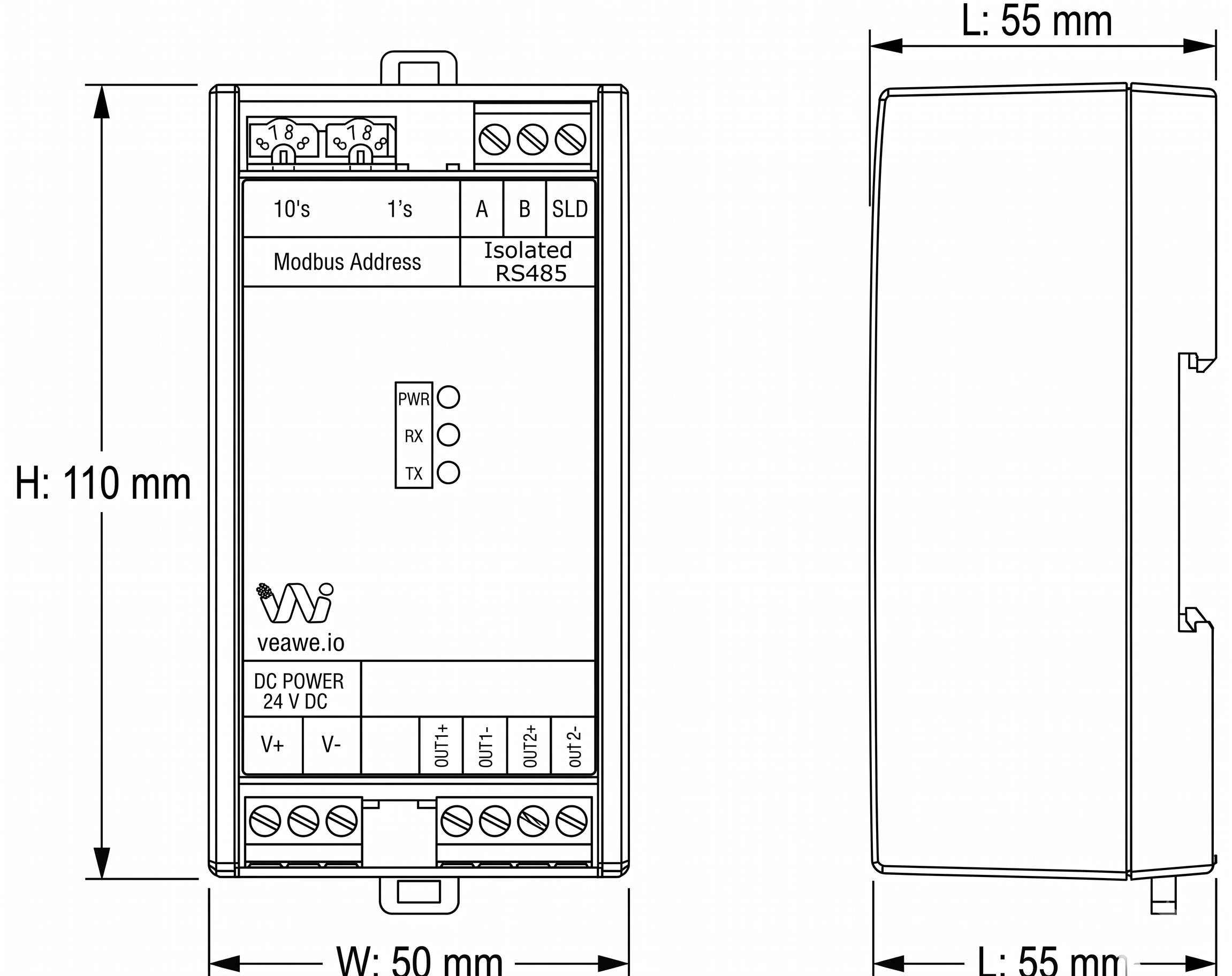
- Dimensions: 110mm × 50mm × 55mm
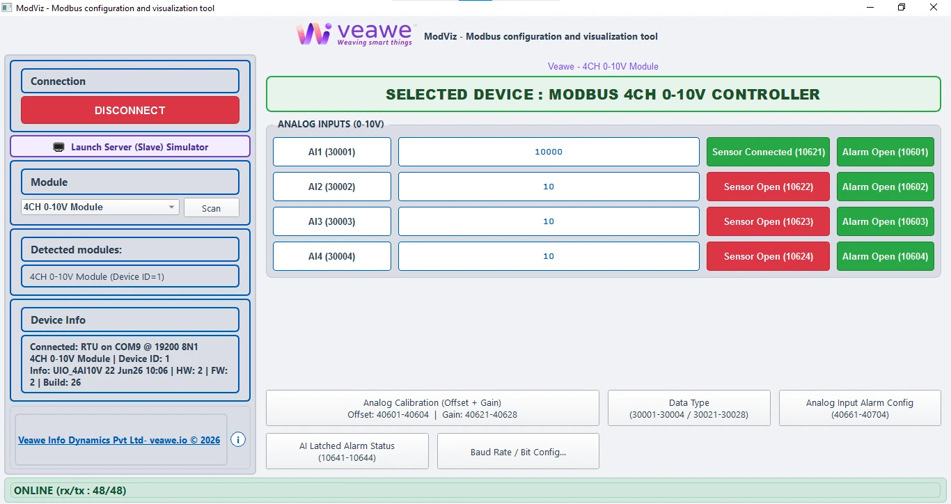
ModViz – Modbus Configuration & Visualization Tool
ModViz is a powerful yet simple configuration and visualization tool designed to work seamlessly with Veawe Modbus I/O modules. It enables engineers, system integrators, and technicians to quickly configure, monitor, and test field devices through an intuitive graphical interface.
The software can be downloaded from https://veawe.io/modviz/
Ordering Information
| Product Code | Description |
|---|---|
| UIO-4IN-10V | 4-Channel Analog Input Module (0–10V DC) |
| UIO-4IN-20MA | 4-Channel Analog Input Module (0–20mA) |
| MIO-2AI-VI | 2-Channel Analog Input Module (0–20mA / 0–36V DC) |
| UIO-8IN-20MA | 8-Channel Analog Input Module (0–20mA) |
| UIO-444-20mA | 4-Channel Analog Input with DI and DO |
Applications
- Industrial Automation – Monitor 0–10V analog sensors in PLC and SCADA systems
- Process Monitoring – Measure voltage signals from transmitters and sensors
- Energy & Utilities – Monitor voltage-based process parameters from field instrumentation
- Building Management – Integrate 0–10V sensors for HVAC, power monitoring, and environment control
- Remote Monitoring – Ideal for distributed installations and remote data acquisition
Specifications
| Parameter | Value |
|---|---|
| Mounting | DIN rail |
| Dimensions | 110 mm x 50 mm x 55 mm (L x W x H) |
Electrical Specifications
| Parameter | Value |
|---|---|
| Supply Voltage | 15–24V DC |
| Analog Input Range | 0–10V DC |
| Communication Port | RS-485 |
Input/Output Specifications
| Parameter | Value |
|---|---|
| Channel Count | 4 |
| Signal Range | 0–10V |
| Resolution | 0.001V |
Isolation & Protection Specifications
| Parameter | Value | Notes / Description |
|---|---|---|
| Supply Reverse Polarity Protection | Integrated | Series protection diode (continuous protection, zero reverse leakage) |
| Supply Isolation | Non-Isolated | Common ground between input power, internal circuitry, analog inputs |
| Transient Voltage Clamping | Up to 600W | Clamps overvoltage spikes (10/100 µs peak pulse rating) |
| EMC & Immunity Standards | Class-Compliant | Meets IEC 61000-4-2 (ESD), IEC 61000-4-4 (EFT), & IEC 61000-4-5 (Surge) |
| RS-485 Bus ESD Protection | 15kV HBM/Air | IEC61000-4-2 Integrated high-ESD protected transceiver on A/B lines |
Mechanical Dimensions
Terminal Details
Top Connector – RS-485
| Pin | 1 | 2 | 3 |
|---|---|---|---|
| Signal | A | B | Shield |
Analog input Connector
| Pin | 1 | 2 | 3 | 4 | 5 | 6 | 7 | 8 |
|---|---|---|---|---|---|---|---|---|
| Signal | CH1+ | CH1- | CH2+ | CH2- | CH3+ | CH3- | CH4+ | CH4- |
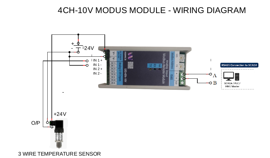
Wiring Diagrams
Note: All images and connection diagrams shown are for illustrative purposes only and may differ from the actual product.
Communication Interface
| Protocol | Physical Layer | Default Baud Rate | Default Format |
|---|---|---|---|
| Modbus RTU | RS-485 | 19200 | 8N1 |
Basic Process Registers
| Signal | Address | Type | Description |
|---|---|---|---|
| AI1–AI4 (0–10V) | 30001–30004 / 30021–30028 | int16 / float | Raw analog (0.001V) / Scaled engineering value |
Supported Modbus Function Codes
| Read | Write |
|---|---|
| 01 – Read Coils | 05 – Write Single Coil |
| 02 – Read Discrete Inputs | 06 – Write Single Register |
| 03 – Read Holding Registers | 15 – Write Multiple Coils |
| 04 – Read Input Registers | 16 – Write Multiple Registers |
Register Map Overview
| Function | Address Range | Type | Description |
|---|---|---|---|
| Discrete Inputs | 10601–10604 | Bit | AI1 to AI4 alarm indication |
| Discrete Inputs | 10621–10624 | Bit | AI1 to AI4 sensor open indication |
| Discrete Inputs | 10641–10644 | Bit | AI1 to AI4 latched alarm indication |
| Coils | 00601–00604 | Bit | Reset AI alarm counter |
| Input Registers | 30001–30004 | int16 | AI1 to AI4 raw value |
| Input Registers | 30021–30028 | float | AI1 to AI4 scaled value |
| Input Registers | 30601–30604 | int16 | AI1 to AI4 alarm counters |
| Holding Registers | 40101 | int16 | Slave address |
| Holding Registers | 40102 | int16 | Baud rate selection |
| Holding Registers | 40103 | int16 | Serial format |
| Holding Registers | 40601–40604 | int16 | AI1 to AI4 offset |
| Holding Registers | 40621–40628 | float | AI1 to AI4 gain |
| Holding Registers | 40661–40664 | int16 | AI1 to AI4 alarm mode |
| Holding Registers | 40681–40684 | int16 | AI1 to AI4 alarm minimum |
| Holding Registers | 40701–40704 | int16 | AI1 to AI4 alarm maximum |
Detailed Register Tables
Discrete Inputs (1xxxx)
Analog Input Live Alarm Status
| Function | Address Range | Type | Description |
|---|---|---|---|
| Discrete Inputs | 10601–10604 | Bit | AI1 to AI4 alarm indication |
If an analog sensor vale is out of the range set in Alarm Configuration:
- Alarm indication status bit is set
Analog Sensor Open Status
| Function | Address Range | Type | Description |
|---|---|---|---|
| Discrete Inputs | 10621–10624 | Bit | AI1 to AI4 sensor open indication |
If an analog sensor is disconnected or open: ▪ Analog value reads as 0.000V ▪ Corresponding sensor open status bit is set
Analog Input Latched Alarm Status
| Function | Address Range | Type | Description |
|---|---|---|---|
| Discrete Inputs | 10641–10644 | Bit | AI1 to AI4 latched alarm status, Auto clears on read |
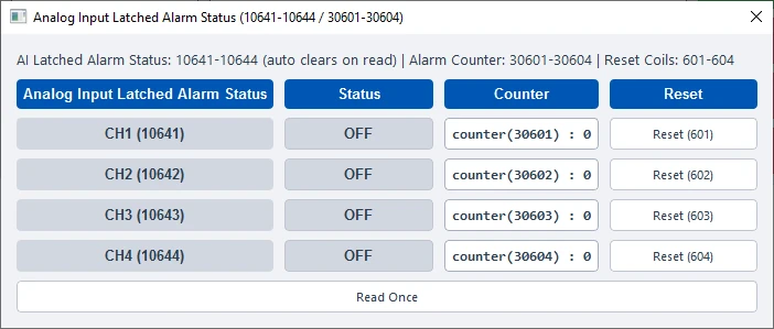
Latched alarm status stays high even after the alarm is cleared and auto clears only after the master reads this bit
Coils (0xxxx)
AI Alarm Counter Reset
| Function | Address Range | Type | Description |
|---|---|---|---|
| Coils | 00601–00604 | Bit | Reset AI alarm counter |
Writing 1 to the coil resets the corresponding Retentive Alarm counter value, This bit is self clearing
Input Registers (3xxxx)
Analog Input Values
| Function | Address Range | Type | Description |
|---|---|---|---|
| Input Registers | 30001–30004 | int16 | AI1 to AI4 raw value |
| Input Registers | 30021–30028 | float | AI1 to AI4 scaled value |
| Input Registers | 30601–30604 | int16 | AI1 to AI4 alarm counters |
Holding Registers (4xxxx)
Analog Input Calibration
| Function | Address Range | Type | Description |
|---|---|---|---|
| Holding Registers | 40601–40604 | int16 | AI1 to AI4 offset |
| Holding Registers | 40621–40628 | float | AI1 to AI4 gain |
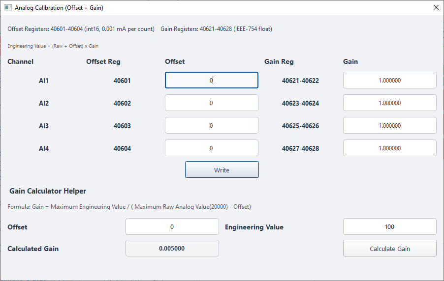
Examples: Offset value 1000 = +1.000V Gain value 0.005 = multiplier correction
Analog Input Alarm Configuration
| Function | Address Range | Type | Description |
|---|---|---|---|
| Holding Registers | 40661–40664 | int16 | AI1 to AI4 alarm mode |
| Holding Registers | 40681–40684 | int16 | AI1 to AI4 alarm minimum |
| Holding Registers | 40701–40704 | int16 | AI1 to AI4 alarm maximum |
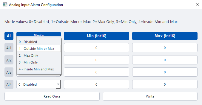
Alarm Modes Values: -
0 = Disabled
1 = Outside minimum or maximum 2 = Maximum only
4 = Inside minimum and maximum window 3 = Minimum only
Communication Settings
| Address | Type | Description |
|---|---|---|
| 40101 | int16 | Modbus server (slave) address (switch value) |
| 40102 | int16 | Baud rate selection |
| 40103 | int16 | Serial format selection |
| 40104 | int16 | Serial device mode. 0 = Server (slave), 1 = Client (master) |
| 40105 | int16 | Remote read/write poll interval. Example: 10 = 1 second |
Modbus Address (40101)
This is set using the rotary or DIP switches.
Baud Rate Register (40102) and Serial Format Register (40103)
| Value | Baud Rate | Value | Baud Rate | Value | Format |
|---|---|---|---|---|---|
| 0 | 300 | 7 | 9600 | 0 | 8N1 |
| 1 | 600 | 8 | 14400 | 1 | 8E1 |
| 2 | 1200 | 9 | 19200 | 2 | 8O1 |
| 3 | 1800 | 10 | 38400 | 3 | 8N2 |
| 4 | 2400 | 11 | 57600 | 4 | 8E2 |
| 5 | 4800 | 12 | 62500 | 5 | 8O2 |
| 6 | 7200 | 13 | 115200 |
Default: 19200 baud, 8N1.
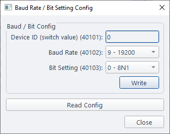
Default Settings
| Setting | Default |
|---|---|
| Slave Address | As per switch position |
| Baud Rate | 19200 |
| Serial Format | 8N1 |
Configuration Settings
Default Mode
Default mode is useful when communication settings are unknown.
When the rotary address switch is set to 00:
- Server address = 1
- Baud rate = 19200
- Serial format = 8N1
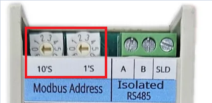
Changing to default mode does not overwrite stored settings. Stored settings remain unchanged until written through Modbus.
LED Indications and Diagnostics
| LED | Description |
|---|---|
| Power | Module power ON indication |
| Tx | RS-485 transmit activity |
| Rx | RS-485 receive activity |
Calibration and Engineering Values
The module internally measures analog voltage input as a raw integer value.
Example:
- 0V = 0
- 1V = 1000
- 5V = 5000
- 10V = 10000
Raw values are stored in int16 registers with a resolution of 0.001V.
Engineering value registers allow the raw voltage value to be converted into user units such as pressure, temperature, tank level, flow, weight, and percentage.
| Sensor Type | Input Range | Engineering Value Range |
|---|---|---|
| Pressure Transmitter | 1–10V | 0 to 10.0 Bar |
| Tank Level Sensor | 0–10V | 0 to 100% |
| Temperature Transmitter | 0–5V | 0 to 200°C |
Engineering values are available in float format using IEEE754 registers.
Formula:
Engineering Value = (Raw Value + Offset) × Gain
Where:
- Raw Value = measured voltage in 0.001V units
- Offset = calibration correction in 0.001V units
- Gain = engineering unit multiplier
Example:
- Raw input = 5000
- Offset = 0
- Gain = 0.01
- Engineering value = 50
This can be used for a transmitter scaled from 0–10V to 0–200°C.
ModViz’s Gain Calculator helper can be used to easily calculate offset and gain values.
Revision History
| Revision | Date | Description of Change |
|---|---|---|
| Rev 1.0 | 2026-08-10 | Initial datasheet release |
Get the latest version of this datasheet : click here..
Support
Website: www.veawe.io
Email: info@veawe.io