Isolated Analog Signal Converter 70V to...

The AC-70V-10V is an industrial precision high-voltage analog signal conditioner designed to convert 0–70V DC voltage levels into a standardized, isolated 0–10V DC instrumentation signal. Built with a pure linear analog isolation amplifier without PWM conversion or digital reconstruction, it achieves an ultra-fast response time (< 1 ms) and exceptional signal fidelity (< ±0.1% output ripple). With a robust 4.25 kV RMS galvanic isolation barrier between high-voltage input and low-voltage control circuitry, it safely steps down and isolates 48V telecom rectifier buses, 48V motive battery banks, and solar energy systems, protecting sensitive PLC and DCS analog input cards from dangerous ground loops and electrical transients.
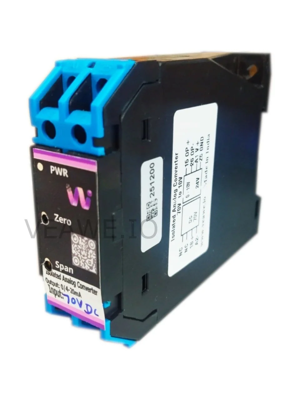
Key Features
- 0–70V DC input to 0–10V DC isolated linear conversion
- 4.25 kV RMS galvanic isolation between input and output
- 1.5 kV RMS isolation between input and auxiliary power
- Ultra-fast response time (< 1 ms) for battery and bus telemetry
- Low output ripple noise (< ±0.1%) with ±0.2% full-scale accuracy
- Pure analog linear amplifier topology with zero digital sampling artifacts
- Front-panel multi-turn Zero and Span calibration potentiometers
- 24V DC auxiliary power supply (18V to 30V DC operating range)
- Compact 22 mm DIN rail and wall mountable enclosure
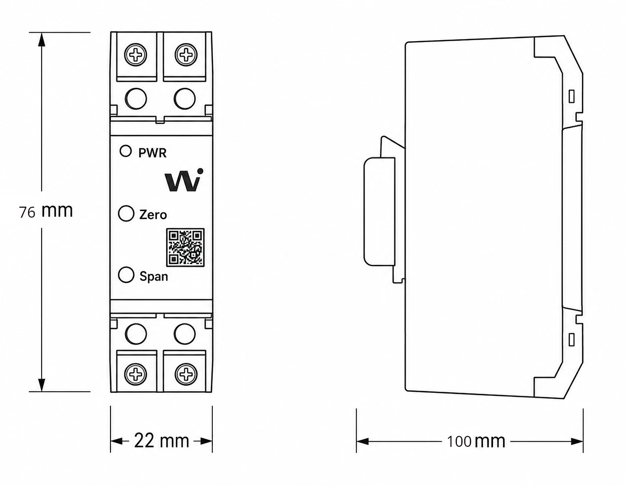
- Dimensions: 100 mm × 76 mm × 22 mm
Ordering Information
| Product Code | Description |
|---|---|
| AC-70V-10V | Isolated High Voltage Converter 0–70V DC to 0–10V DC (24V DC, 4.25kV Isolation) |
| AC-70V-420 | Isolated High Voltage Converter 0–70V DC to 4–20mA |
| AC-150V-10V | Isolated High Voltage Converter 0–150V DC to 0–10V DC |
| AC-300V-10V | Isolated High Voltage Converter 0–300V DC to 0–10V DC |
| SPD-24V-DC | Surge Protection Device 24V DC SPD |
| USS10V24V-D | Voltage Source Simulator 0–10V with Digital Display |
Applications
- Telecom -48V DC Power Plant Monitoring: Continuous voltage tracking of -48V DC rectifier power banks with complete isolation.
- 48V Motive & Forklift Battery Systems: Safe battery string voltage sensing for industrial electric vehicle charging stations.
- Solar Off-Grid Power Systems: Monitoring 48V photovoltaic battery charging systems directly into standard automation controllers.
- Industrial Automation & Process Control: Reliable signal interfacing across long cable runs with floating ground potentials.
- Control Panel Building: Space-efficient 22 mm DIN rail installation for DC distribution switchboards.
Specifications
| Parameter | Value |
|---|---|
| Mounting Type | 35 mm DIN Rail & Wall Mounting |
| Dimensions | 100 mm x 76 mm x 22 mm (L x H x W) |
| Weight | 100 g |
| Enclosure Material | Industrial Grade ABS |
| Operating Temperature | 0 °C to +50 °C (Industrial: -10 °C to +60 °C) |
| Storage Temperature | -40 °C to +85 °C |
| Relative Humidity | 5% to 95% RH (non-condensing) |
Electrical Specifications
| Parameter | Specification |
|---|---|
| Power Supply Voltage | 24V DC \(\pm 25\%\) (18V to 30V DC) |
| Operating Current | 100 mA @ 24V DC |
| Input Signal Range | 0.0 V to 70.0 V DC (High Voltage DC) |
| Input Impedance | \(> 500\,\text{k}\Omega\) |
| Output Signal Range | 0.00 V to 10.00 V DC (Load \(\ge 2\,\text{k}\Omega\)) |
| Conversion Accuracy | \(\pm 0.2\%\) of Full Scale @ 25 °C (max \(\pm 0.5\%\)) |
| Output Ripple Noise | \(< \pm 0.1\%\) of Full Scale |
| Response Time | \(< 1\text{ ms}\) (< 1 milliSec) |
| Temperature Drift | \(< 100\text{ ppm} / \text{°C}\) |
| Status Indication | Power LED ON (PWR) |
| Field Calibration | Front-panel multi-turn Zero and Span trimpots |
Isolation & Protection Specifications
| Parameter | Value | Standard / Notes |
|---|---|---|
| Galvanic Isolation (Input to Output) | 4,250 V RMS (4.25 kV) | Optical & magnetic isolation barrier (1 min) |
| Galvanic Isolation (Input to Aux. Power) | 1,500 V RMS (1.5 kV) | Continuous dielectric isolation |
| Output to Aux. Supply | Shared Common Ground | Non-isolated reference ground |
| Reverse Polarity Protection | Integrated | Protects internal circuitry against reverse DC supply wiring |
| Transient Clamping | 600W TVS | Surge and spike suppression across all ports |
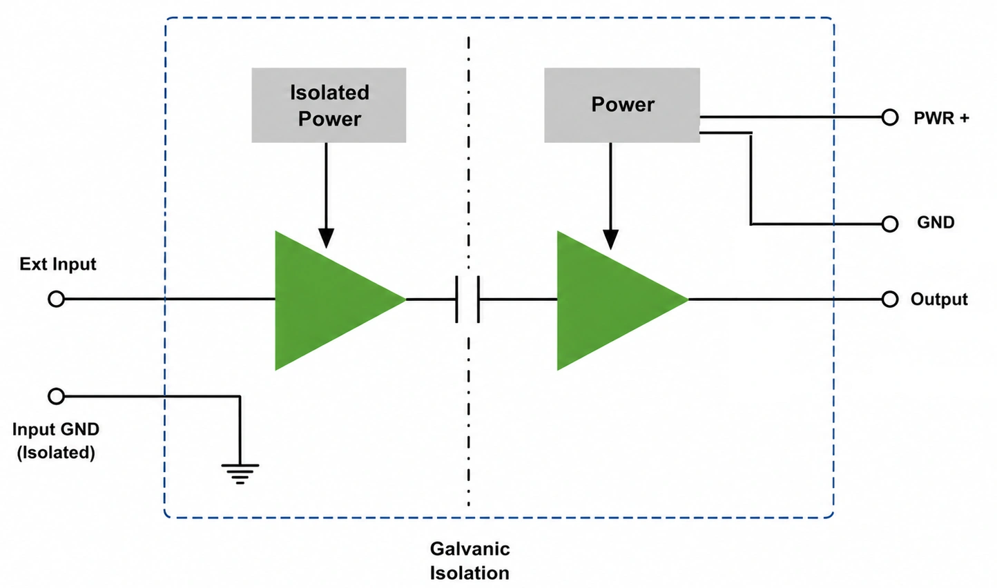
Functional Isolation Architecture & Dynamic Response
The pure linear analog architecture provides true continuous signal isolation without quantization stepping or switching ripples.
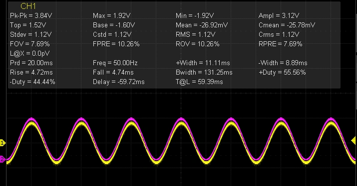
Oscilloscope Dynamic Waveform Verification
Oscilloscope measurement verifying that the isolated output signal reproduces the input waveform with sub-millisecond response latency (< 1 ms) and clean signal fidelity:
Mechanical Dimensions
Terminal Details & Wiring
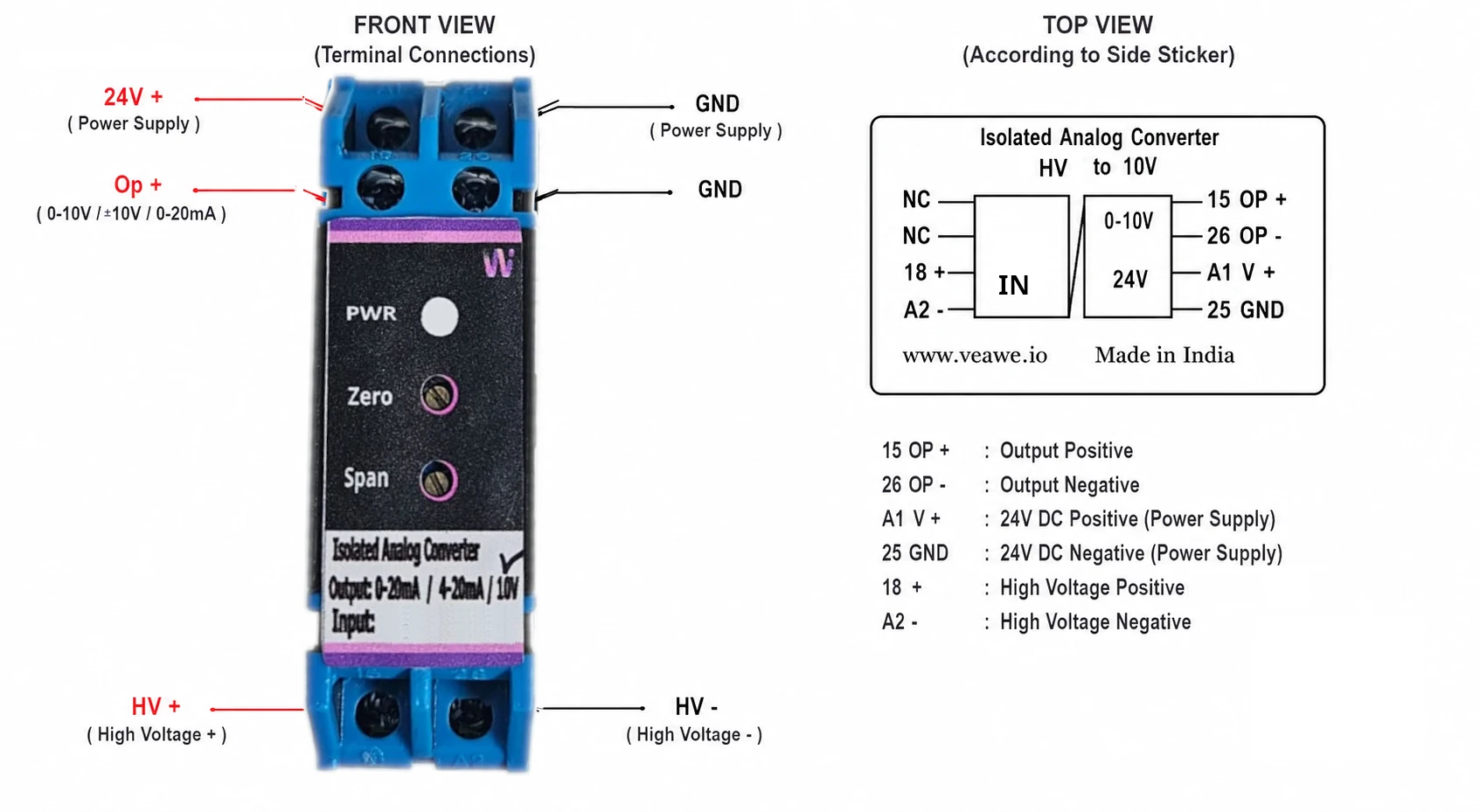
Connection Pinouts
| Terminal Block | Pin | Label | Signal | Description |
|---|---|---|---|---|
| Input Terminals | 18 | 18 + | HV Input (+) | 0–70V DC High Voltage Input (+) |
| (Bottom Block) | A2 | A2 - | HV Input (-) | High Voltage Input Ground Return (-) |
| – | NC | Unused | Reserved / Not Connected | |
| – | NC | Unused | Reserved / Not Connected | |
| Output Terminals | 15 | 15 OP+ | Output (+) | Calibrated 0–10V DC Analog Output (+) |
| (Top Block) | 26 | 26 OP- | Output (-) | Analog Output Ground Return (-) |
| Power Terminals | A1 | A1 V+ | +24V DC | Auxiliary Power Supply Input (+24V DC) |
| (Top Block) | 25 | 25 GND | Power 0V | Auxiliary Power Supply Ground Return |
Available Variants & Configurations
The Veawe Precision Analog Isolator family is available in standardized and custom input/output configurations:
| Signal Converter Input | Output | High Voltage Input | Output | Transducer Input | Output |
|---|---|---|---|---|---|
| 0–20 mA | 0–20mA, 4–20mA, 0–10V, ±10V | 30V DC | 0–20mA, 4–20mA, 0–10V | Pt100 | 0–20mA, 4–20mA, 0–10V |
| 4–20 mA | 0–20mA, 4–20mA, 0–10V, ±10V | 70V DC | 0–20mA, 4–20mA, 0–10V | Pt1000 | 0–20mA, 4–20mA, 0–10V |
| 0–10 V DC | 0–20mA, 4–20mA, 0–10V, ±10V | 100V DC | 0–20mA, 4–20mA, 0–10V | K type | 0–20mA, 4–20mA, 0–10V |
| 0–5 V DC | 0–20mA, 4–20mA, 0–10V, ±10V | 150V DC | 0–20mA, 4–20mA, 0–10V | J type | 0–20mA, 4–20mA, 0–10V |
| 75 mV DC | 0–20mA, 4–20mA, 0–10V, ±10V | 300V / ±300V DC | 0–20mA, 4–20mA, 0–10V | Resistance | 0–20mA, 4–20mA, 0–10V |
| ±75 mV DC | 0–20mA, 4–20mA, 0–10V, ±10V | 350V DC | 0–20mA, 4–20mA, 0–10V | — | — |
| — | — | 100V AC | 0–20mA, 4–20mA, 0–10V | — | — |
| — | — | 5A AC (CT) | 0–20mA, 4–20mA, 0–10V | — | — |
LED Indications and Diagnostics
| LED | Color | Status | Description |
|---|---|---|---|
| PWR | Green | ON | Auxiliary 24V DC operating power connected and regulated |
Revision History
| Revision | Date | Description of Change |
|---|---|---|
| Rev 1.0 | 2026-09-09 | Initial datasheet release |
Get the latest version of this datasheet : click here..
Support
Website: www.veawe.io
Email: info@veawe.io