8AI Modbus Remote I/O Module

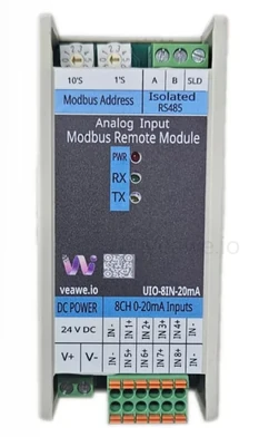
Compact Modbus RTU remote I/O module with eight 0–20mA analog inputs, configurable alarm logic.
Key Features
- 8 Channel 0–20mA Analog Inputs
- 16-bit analog resolution
- Factory calibrated accuracy: ± 0.1% from upper-range
- Raw analog value resolution in steps of 0.001mA
- Sensor open / broken wire indication
- Configurable individual alarms indication
- Retentive alarm counters on power cycle
- Individual channel offset and gain calibration
- Integer and IEEE754 float value support
- Modbus RTU over Isolated RS-485
- Modbus RTU remote write master mode
- Easy to use free ModViz software
- Rotary address switch for address selection from 1 to 99
- Wide Supported baud rates from 300 to 115200
- DIN rail mountable
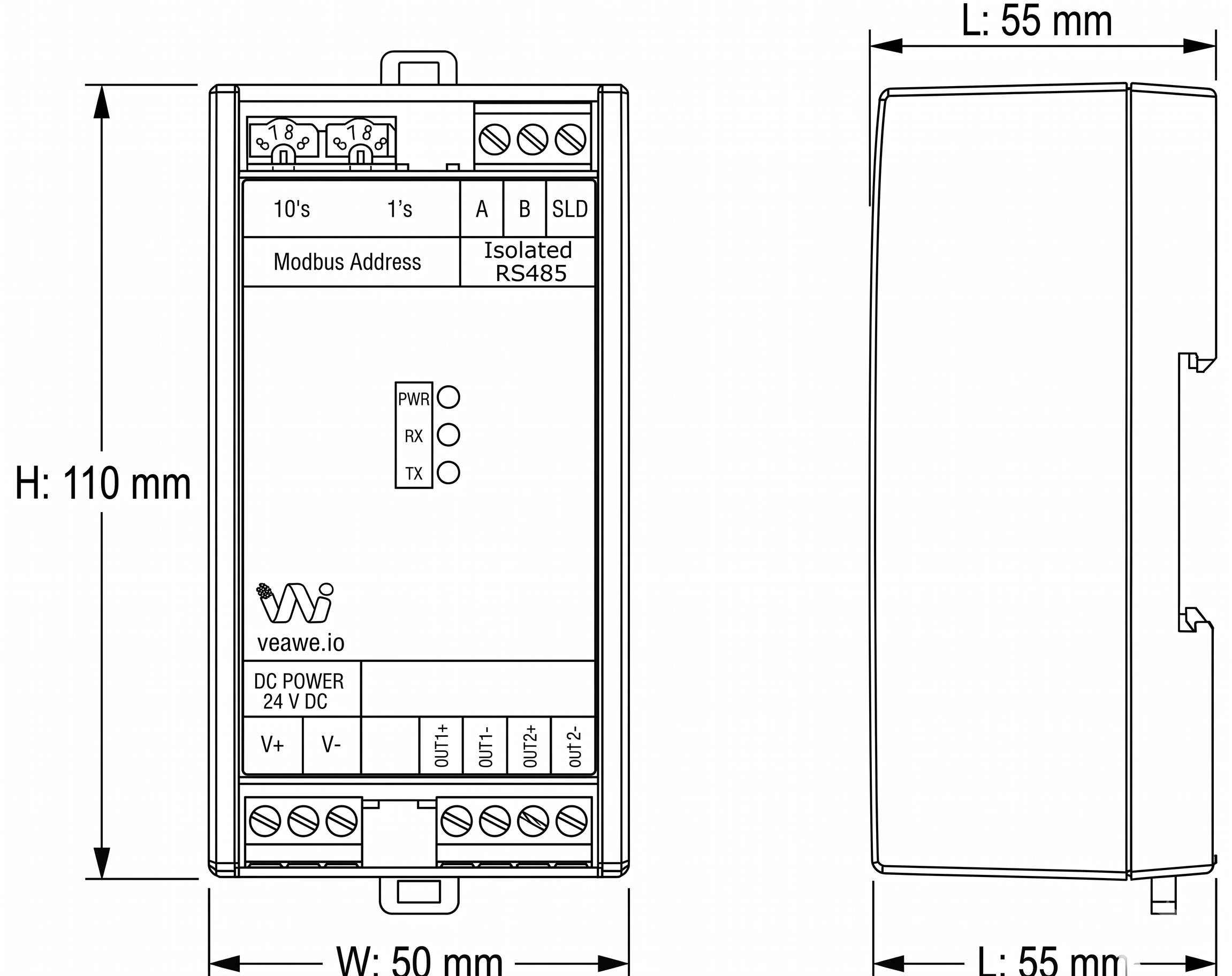
- Dimensions: 110mm × 50mm × 55mm
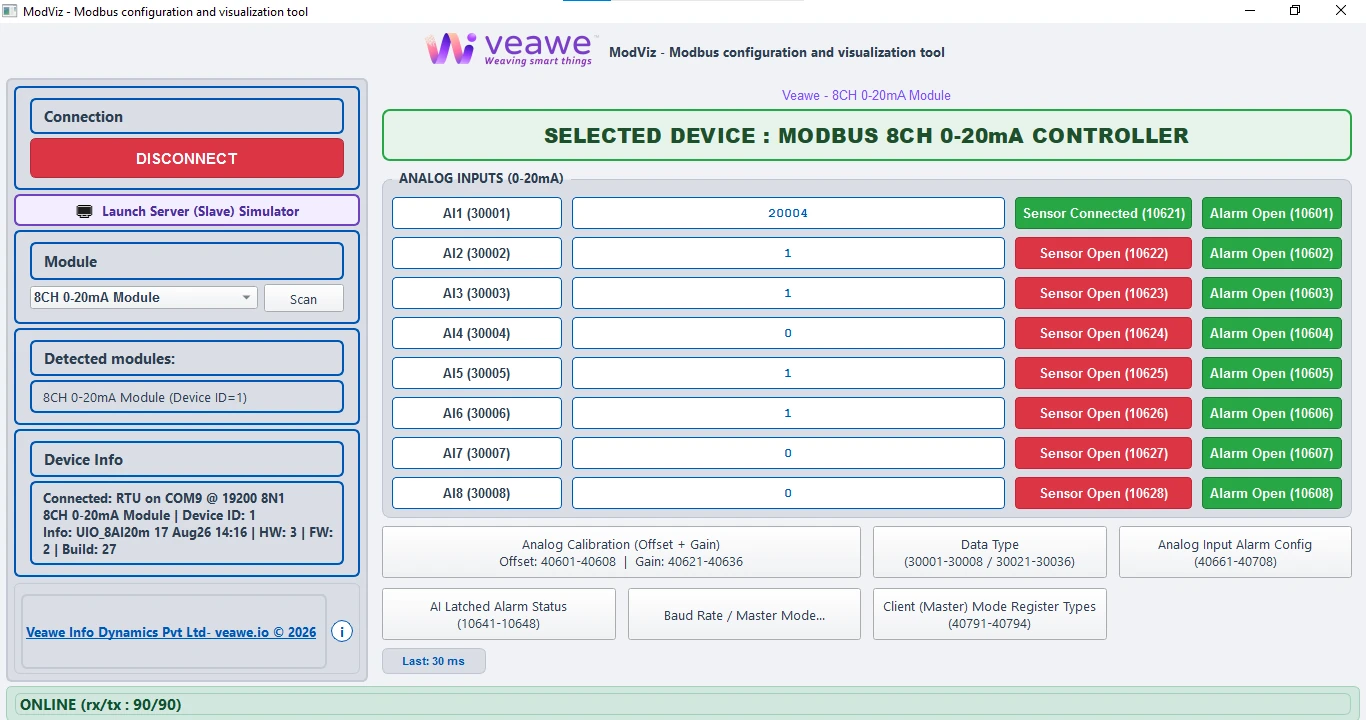
ModViz – Modbus Configuration & Visualization Tool
ModViz is a powerful yet simple configuration and visualization tool designed to work seamlessly with Veawe Modbus I/O modules. It enables engineers, system integrators, and technicians to quickly configure, monitor, and test field devices through an intuitive graphical interface.
The software can be downloaded from https://veawe.io/modviz/
Ordering Information
| Product Code | Description |
|---|---|
| UIO-8IN-20MA | 8-Channel Analog Input Module (0–20mA) |
| UIO-4IN-20MA | 4-Channel Analog Input Module (0–20mA) |
| MIO-2AI-VI | 2-Channel Analog Input Module (0–20mA / 0–36V DC) |
| UIO-4IN-10V | 4-Channel Analog Input Module (0–10V DC) |
| UIO-444-20mA | 4-Channel Analog Input with DI and DO |
Applications
- Industrial Automation – Monitor 4–20mA analog sensors across up to 8 channels in PLC and SCADA systems
- Process Monitoring – Measure current loop signals from transmitters and sensors on high-density installations
- Energy & Utilities – Monitor current-based process parameters from field instrumentation
- Remote Monitoring – Ideal for distributed installations and remote data acquisition
- Modbus Gateway – Master Mode writes AI1–AI8 values to a remote Modbus slave device, retransmitting analog values to legacy PLCs or building a Modbus-to-analog gateway
Specifications
| Parameter | Value |
|---|---|
| Mounting | DIN rail |
| Dimensions | 110 mm x 50 mm x 55 mm (L x W x H) |
Electrical Specifications
| Parameter | Value |
|---|---|
| Supply Voltage | 15–24V DC |
| Analog Input Range | 0–20mA |
| Communication Port | RS-485 |
Input/Output Specifications
| Parameter | Value |
|---|---|
| Channel Count | 8 |
| Signal Range | 0–20mA |
| Resolution | 0.001 mA |
Isolation & Protection Specifications
| Parameter | Value | Notes / Description |
|---|---|---|
| Supply Reverse Polarity Protection | Integrated | Series protection diode (continuous protection, zero reverse leakage) |
| Supply Isolation | Non-Isolated | Common ground between input power, internal circuitry, analog outputs |
| Transient Voltage Clamping | Up to 600W | Clamps overvoltage spikes (10/100 µs peak pulse rating) |
| EMC & Immunity Standards | Class-Compliant | Meets IEC 61000-4-2 (ESD), IEC 61000-4-4 (EFT), & IEC 61000-4-5 (Surge) |
| RS-485 Bus ESD Protection | 15kV HBM/Air | IEC61000-4-2 Integrated high-ESD protected transceiver on A/B lines |
| RS-485 Isolation | 2.5kVrms | Isolated RS485 signal with other circuitry |
Mechanical Dimensions
Terminal Details
Top Connector – RS-485
| Pin | 1 | 2 | 3 |
|---|---|---|---|
| Signal | A | B | Shield |
Analog input Connector
| Pin | 1 | 2 | 3 | 4 | 5 | 6 |
|---|---|---|---|---|---|---|
| Signal | GND | CH1+ | CH2+ | CH3+ | CH4+ | GND |
| Pin | 7 | 8 | 9 | 10 | 11 | 12 |
| Signal | GND | CH5+ | CH6+ | CH7+ | CH8+ | GND |
Wiring Diagrams
Note: All images and connection diagrams shown are for illustrative purposes only and may differ from the actual product.

Communication Interface
| Protocol | Physical Layer | Default Baud Rate | Default Format |
|---|---|---|---|
| Modbus RTU | RS-485 | 19200 | 8N1 |
Basic Process Registers
| Signal | Address | Type | Description |
|---|---|---|---|
| AI1–AI8 (0–20mA) | 30001–30008 / 30021–30036 | int16 / float | Raw analog (0.001mA) / Scaled engineering value |
Supported Modbus Function Codes
| Read | Write |
|---|---|
| 01 – Read Coils | 05 – Write Single Coil |
| 02 – Read Discrete Inputs | 06 – Write Single Register |
| 03 – Read Holding Registers | 15 – Write Multiple Coils |
| 04 – Read Input Registers | 16 – Write Multiple Registers |
Register Map Overview
| Function | Address Range | Type | Description |
|---|---|---|---|
| Discrete Inputs | 10601–10608 | Bit | AI1 to AI8 alarm indication |
| Discrete Inputs | 10621–10628 | Bit | AI1 to AI8 sensor open indication |
| Discrete Inputs | 10641–10648 | Bit | AI1 to AI8 latched alarm indication |
| Coils | 00601–00608 | Bit | Reset AI alarm counter |
| Input Registers | 30001–30008 | int16 | AI1 to AI8 raw value |
| Input Registers | 30021–30036 | float | AI1 to AI8 scaled value |
| Input Registers | 30601–30608 | int16 | AI1 to AI8 alarm counters |
| Holding Registers | 40101 | int16 | Slave address |
| Holding Registers | 40102 | int16 | Baud rate selection |
| Holding Registers | 40103 | int16 | Serial format |
| Holding Registers | 40601–40608 | int16 | AI1 to AI8 offset |
| Holding Registers | 40621–40636 | float | AI1 to AI8 gain |
| Holding Registers | 40661–40668 | int16 | AI1 to AI8 alarm mode |
| Holding Registers | 40681–40688 | int16 | AI1 to AI8 alarm minimum |
| Holding Registers | 40701–40708 | int16 | AI1 to AI8 alarm maximum |
Detailed Register Tables
Discrete Inputs (1xxxx)
Analog Input Live Alarm Status
| Function | Address Range | Type | Description |
|---|---|---|---|
| Discrete Inputs | 10601–10608 | Bit | AI1 to AI8 alarm indication |
If an analog sensor vale is out of the range set in Alarm Configuration:
- Alarm indication status bit is set
Analog Sensor Open Status
| Function | Address Range | Type | Description |
|---|---|---|---|
| Discrete Inputs | 10621–10628 | Bit | AI1 to AI8 sensor open indication |
If an analog sensor is disconnected or open:
- Analog value reads as 0.000mA
- Corresponding sensor open status bit is set
Analog Input Latched Alarm Status
| Function | Address Range | Type | Description |
|---|---|---|---|
| Discrete Inputs | 10641–10648 | Bit | AI1 to AI8 latched alarm status, Auto clears on read |
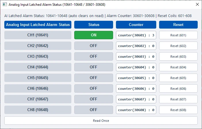
Latched alarm status stays high even after the alarm is cleared and auto clears only after the master reads this bit
Coils (0xxxx)
AI Alarm Counter Reset
| Function | Address Range | Type | Description |
|---|---|---|---|
| Coils | 00601–00608 | Bit | Reset AI alarm counter |
Writing 1 to the coil resets the corresponding Retentive Alarm counter value, This bit is self clearing
Input Registers (3xxxx)
Analog Input Values
| Function | Address Range | Type | Description |
|---|---|---|---|
| Input Registers | 30001–30008 | int16 | AI1 to AI8 raw value |
| Input Registers | 30021–30036 | float | AI1 to AI8 scaled value |
| Input Registers | 30601–30608 | int16 | AI1 to AI8 alarm counters |
Holding Registers (4xxxx)
Analog Input Calibration
| Function | Address Range | Type | Description |
|---|---|---|---|
| Holding Registers | 40601–40608 | int16 | AI1 to AI8 offset |
| Holding Registers | 40621–40636 | float | AI1 to AI8 gain |

Examples: Offset value 1000 = +1.000mA, Gain value 0.005 = multiplier correction
Analog Input Alarm Configuration
| Function | Address Range | Type | Description |
|---|---|---|---|
| Holding Registers | 40661–40668 | int16 | AI1 to AI8 alarm mode |
| Holding Registers | 40681–40688 | int16 | AI1 to AI8 alarm minimum |
| Holding Registers | 40701–40708 | int16 | AI1 to AI8 alarm maximum |
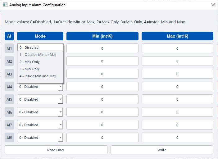
Alarm Modes Values: -
0 = Disabled
1 = Outside minimum or maximum 2 = Maximum only
4 = Inside minimum and maximum window 3 = Minimum only
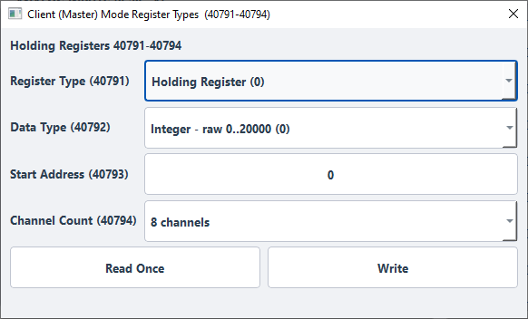
Analog Input Master Mode Configuration
These values are applicable when the device is in Master Mode and 40104 = 1.
| Address | Type | Description |
|---|---|---|
| 40791 | int16 | Remote device destination register type to write. 0 = Holding Register |
| 40792 | int16 | Remote device destination data type to write. 0 = int16 raw data (0 to 20000 for 0~20.000 mA), 1 = float scaled data as per offset and gain, 2 = int16 scaled data as per offset and gain |
| 40793 | int16 | Remote device destination start address |
| 40794 | int16 | Remote destination channel count. Max channels is 8 |
Communication Settings
| Address | Type | Description |
|---|---|---|
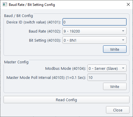
| 40101 | int16 | Modbus server (slave) address (switch value) |
| 40102 | int16 | Baud rate selection |
| 40103 | int16 | Serial format selection |
| 40104 | int16 | Serial device mode. 0 = Server (slave), 1 = Client (master) |
| 40105 | int16 | Remote read/write poll interval. Example: 10 = 1 second |
| 40106 | int16 | Watchdog interval. Example: 10 = 1 second |
| 40107 | int16 | Watchdog action. 0 = Modbus Watchdog Disabled, 1 = Reset Outputs on Modbus Watchdog Expire |
Modbus Address (40101)
This is set using the rotary or DIP switches.
Baud Rate Register (40102) and Serial Format Register (40103)
| Value | Baud Rate | Value | Baud Rate | Value | Format |
|---|---|---|---|---|---|
| 0 | 300 | 7 | 9600 | 0 | 8N1 |
| 1 | 600 | 8 | 14400 | 1 | 8E1 |
| 2 | 1200 | 9 | 19200 | 2 | 8O1 |
| 3 | 1800 | 10 | 38400 | 3 | 8N2 |
| 4 | 2400 | 11 | 57600 | 4 | 8E2 |
| 5 | 4800 | 12 | 62500 | 5 | 8O2 |
| 6 | 7200 | 13 | 115200 |
Default: 19200 baud, 8N1.
Default Settings
| Setting | Default |
|---|---|
| Slave Address | As per switch position |
| Baud Rate | 19200 |
| Serial Format | 8N1 |
Configuration Settings
Default Mode
Default mode is useful when communication settings are unknown.
When the rotary address switch is set to 00:
- Server address = 1
- Baud rate = 19200
- Serial format = 8N1
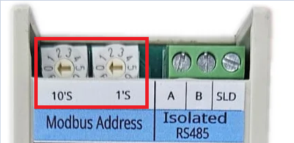
Changing to default mode does not overwrite stored settings. Stored settings remain unchanged until written through Modbus.
Write Remote Device – Master Mode
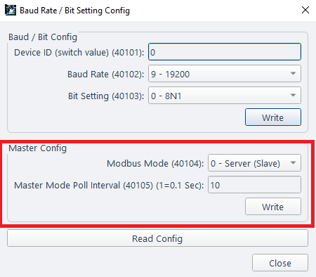
When 40104 is set to 1, the module operates in Modbus Master Mode.
In this mode, the module periodically writes data to another Modbus slave device and automatically updates its analog inputs to the remote device.
Working of Master Mode:
- Master Mode polls the remote device ID as set in the rotary or DIP switch.
- Master Mode polls the remote device at the interval defined by 40105.
- The destination device register type is selected using 40791.
- The destination data type is selected using 40792.
- The start address of the remote data is defined in 40793.
- The number of channels to write is defined in 40794.
- Values of AI1 ~ AI8 are automatically written to the mapped address as per the count.
- If float mode is selected, two Modbus registers are used per channel.
- If int16 mode is selected, one Modbus register is used per channel.
- Offset and gain settings are still applied in Master Mode.
 |
 |
LED Indications and Diagnostics
| LED | Description |
|---|---|
| Power | Module power ON indication |
| Tx | RS-485 transmit activity |
| Rx | RS-485 receive activity |
Calibration and Engineering Values
The module internally measures analog current input as a raw integer value.
Examples:
- 0mA = 0
- 4mA = 4000
- 12mA = 12000
- 20mA = 20000
Raw values are stored in int16 registers with a resolution of 0.001mA.
Engineering value registers allow the raw current value to be converted into user units such as pressure, temperature, tank level, flow, weight, and percentage.
| Sensor Type | Input Range | Engineering Value Range |
|---|---|---|
| Pressure transmitter | 4–20mA | 0 to 10.0 Bar |
| Tank level sensor | 4–20mA | 0 to 100% |
| Temperature transmitter | 4–20mA | 0 to 200°C |
Engineering values are available in float format using IEEE754 registers.
Formula:
Engineering Value = (Raw Value + Offset) × Gain
Where:
- Raw Value = measured current in 0.001mA units
- Offset = calibration correction in 0.001mA units
- Gain = engineering unit multiplier
Example:
- Raw input = 12000
- Offset = -4000
- Gain = 0.01
- Engineering value = 80
This can be used for a transmitter scaled from 0–20mA to -40 to +160°C.
| Raw to mA | Raw Value | Offset | Gain | Result |
|---|---|---|---|---|
| 4–20mA to 0–100% | 12000 | 0 | 0.001 | 50.0% |
| 4–20mA to 0–10 Bar | 12000 | 4000 | 0.00625 | 5 Bar |
| 4–20mA to 0–200°C | 12000 | 4000 | 0.0125 | 100.0°C |
Revision History
| Revision | Date | Description of Change |
|---|---|---|
| Rev 1.0 | 2026-08-10 | Initial datasheet release |
Get the latest version of this datasheet : click here..
Support
Website: www.veawe.io
Email: info@veawe.io