Dual Output Current Source Simulator 0 ...
Dual Output Current Source Simulator 0/4 to 20mA USS20M24V-2P

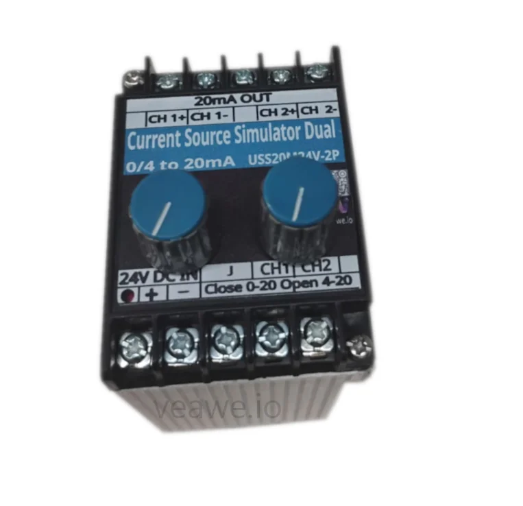
The USS20M24V-2P is an industrial DIN-rail mountable dual-channel 0/4–20mA analog current source simulator. Engineered for control cabinet integration, commissioning, and test benches, it provides two independently adjustable, isolated current outputs in a single compact enclosure. Each channel features its own 5-turn precision adjustment potentiometer and independent jumper configuration for \(0\text{ to }20\text{ mA}\) or \(4\text{ to }20\text{ mA}\) operation.
Key Features
- Dual independent 0/4–20mA current simulator channels
- Two independent 5-turn precision wirewound potentiometers
- Individual channel jumper selection for 0–20mA or 4–20mA range
- High output drive capability powering loads up to 1,100 Ω per channel
- Continuous short-circuit and reverse polarity protection
- 24V DC industrial auxiliary power supply input
- 35 mm DIN rail and wall mountable housing
- Dimensions: 110 mm × 50 mm × 55 mm
Ordering Information
| Product Code | Description |
|---|---|
| USS20M24V-2P | Dual Output Current Source Simulator 0/4 to 20mA (DIN Rail, 24V DC) |
| USS20M24V-D | Current Source Simulator 0/4 to 20mA (with 4-Digit Display, 24V DC) |
| USS20M24V-P | Current Source Simulator 0/4 to 20mA (Without Display, 24V DC) |
| USS10V24V-D | Voltage Source Simulator 0-10V (with 4-Digit Display, 24V DC) |
| ULS20M24V-P | Loop Current Source Simulator 4-20mA (2-Wire, Panel Mount) |
| SPD-20MA | 4-20mA Surge Protection Device |
Applications
- Dual-Channel Transmitter Simulation: Simulating two independent process variables (e.g. temperature and pressure, or inlet and outlet flow) simultaneously.
- Redundant Analog Input Verification: Testing dual-redundant PLC analog input cards and failover voting algorithms.
- Control Cabinet Commissioning: In-cabinet signal injection to test analog loop wiring, I/O mapping, and SCADA graphics without external field simulators.
- Benchtop Testing & R&D Calibration: Convenient bench supply for driving analog transmitters, I/P converters, and proportional valves.
Specifications
| Parameter | Value |
|---|---|
| Mounting Type | Standard 35 mm DIN Rail Mounting |
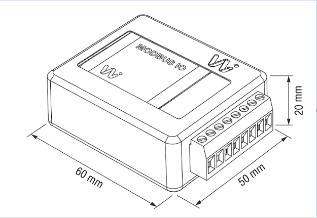
| Dimensions | 70 mm x 50 mm x 85 mm (L x W x H) |
| Enclosure Material | Industrial Grade ABS |
| Operating Temperature | -10 °C to +60 °C |
| Storage Temperature | -40 °C to +85 °C |
| Relative Humidity | 5% to 95% RH (non-condensing) |
Electrical Specifications
| Parameter | Specification |
|---|---|
| Power Supply | 24V DC External |
| Number of Channels | 2 Independent Channels (CH1 and CH2) |
| Output Current Range | 0/4 mA to 20 mA per channel (independent jumper selectable) |
| Output Accuracy | \(\pm 1\%\) of Full Scale |
| Adjustment Mechanism | Dual 5-turn wirewound precision potentiometers |
| Adjustment Resolution | \(\ge 0.01\text{ mA}\) step resolution |
| Load Resistance Range | \(10\,\Omega \text{ to } 1.1\,\text{k}\Omega\) per channel |
| Reverse Polarity Protection | Integrated series protection diode |
| Short Circuit Protection | Continuous electronic current limiting |
Mechanical Dimensions
| Parameter | Value |
|---|---|
| Bezel Dimensions | 48 mm x 48 mm (W x H) |
| Depth Behind Panel | 90 mm (including rear terminals) |
| Panel Cutout | 45 mm x 45 mm (+0.5 mm) |
| Mounting Type | 1/16 DIN Panel Mount with side clamping brackets |
Terminal Details & Wiring
Terminal Connections
The USS20M24V-2P features two rows of heavy-duty screw terminal blocks:
| Terminal Location | Terminal Pin | Label | Function | Description |
|---|---|---|---|---|
| Top Block | 1 | CH 1+ | Channel 1 Output (+) | Channel 1 Active Current Output |
| 2 | CH 1- | Channel 1 Output (-) | Channel 1 Current Return / Signal Ground | |
| 3 | CH 2+ | Channel 2 Output (+) | Channel 2 Active Current Output | |
| 4 | CH 2- | Channel 2 Output (-) | Channel 2 Current Return / Signal Ground | |
| Bottom Block | 1 | + | DC Power Positive | +24V DC Power Supply Input |
| 2 | - | DC Power Negative | 0V / Power Ground Return | |
| 3 | J | Common Jumper Pin | Common terminal for range selection | |
| 4 | CH1 | CH1 Range Jumper | Bridge to J for 0–20mA; Open for 4–20mA | |
| 5 | CH2 | CH2 Range Jumper | Bridge to J for 0–20mA; Open for 4–20mA |
Range Jumper Configuration
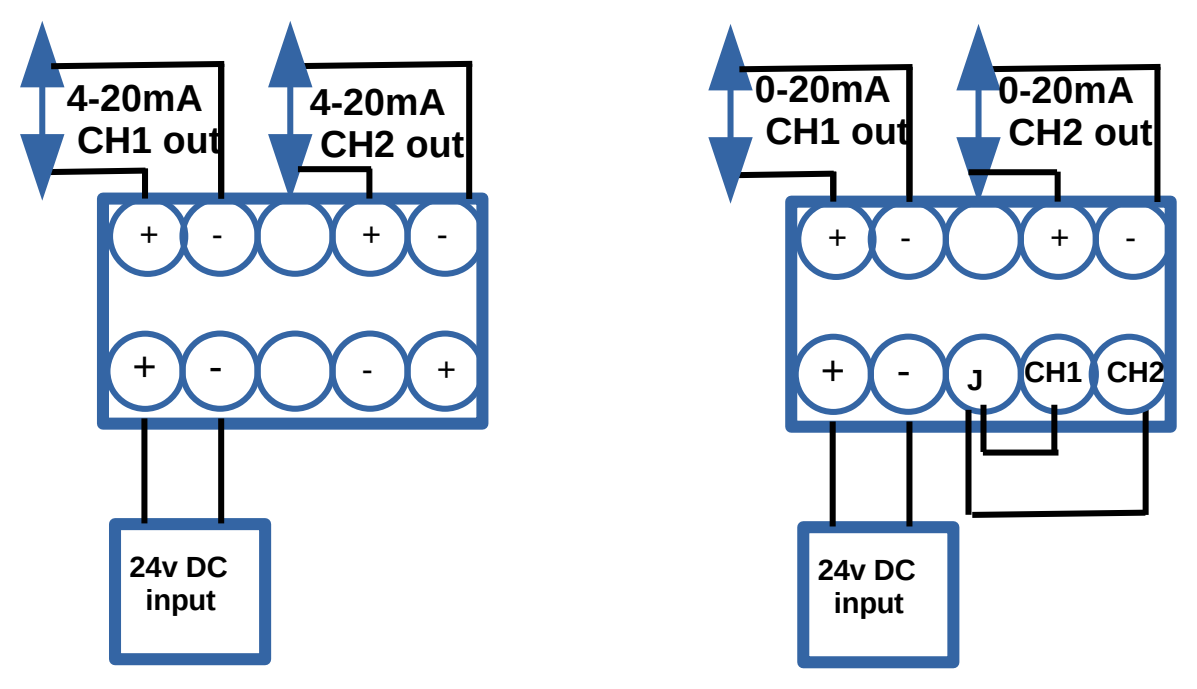
- 4 to 20 mA Mode (Default): Leave jumper pins open (unconnected).
- 0 to 20 mA Mode:
- Connect a jumper wire between terminal J and terminal CH1 for Channel 1.
- Connect a jumper wire between terminal J and terminal CH2 for Channel 2.
Typical Connection Diagram
Revision History
| Revision | Date | Description of Change |
|---|---|---|
| Rev 1.0 | 2026-09-09 | Initial datasheet release |
Get the latest version of this datasheet : click here..
Support
Website: www.veawe.io
Email: info@veawe.io