Isolated RS485 To RS485
Isolated RS485 to RS485 Repeater UC-ISO-485-485

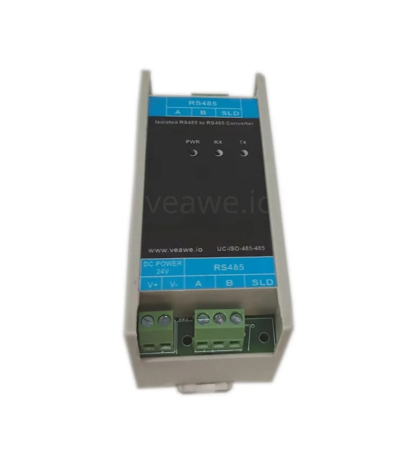
The UC-ISO-485-485 is an industrial-grade optically and galvanically isolated RS485 repeater and signal isolator. It is engineered to extend RS485 communication distances by another 1,200 meters, expand node counts by an additional 256 devices, and break ground loops between distant industrial equipment. With 2.5 kVrms signal isolation and 1 kVrms power isolation, it isolates sensitive PLCs, controllers, and field instruments against common-mode electrical noise and high-voltage line spikes.
Key Features
- 2.5 kV RMS galvanic signal isolation and 1.0 kV RMS power isolation
- Extends RS-485 bus distance up to 1,200 m (4,000 ft)
- Expands network capacity by adding up to 256 nodes per segment
- Hardware automatic send data direction control with zero latency
- Wide supported baud rates from 300 bps to 250 kbps
- ±15 kV ESD and TVS surge protection across all terminals
- Independent LED indicators for Power, TX, and RX
- 9V to 30V DC industrial power supply input (nominal 24V DC)
- 35 mm DIN rail and wall mountable housing
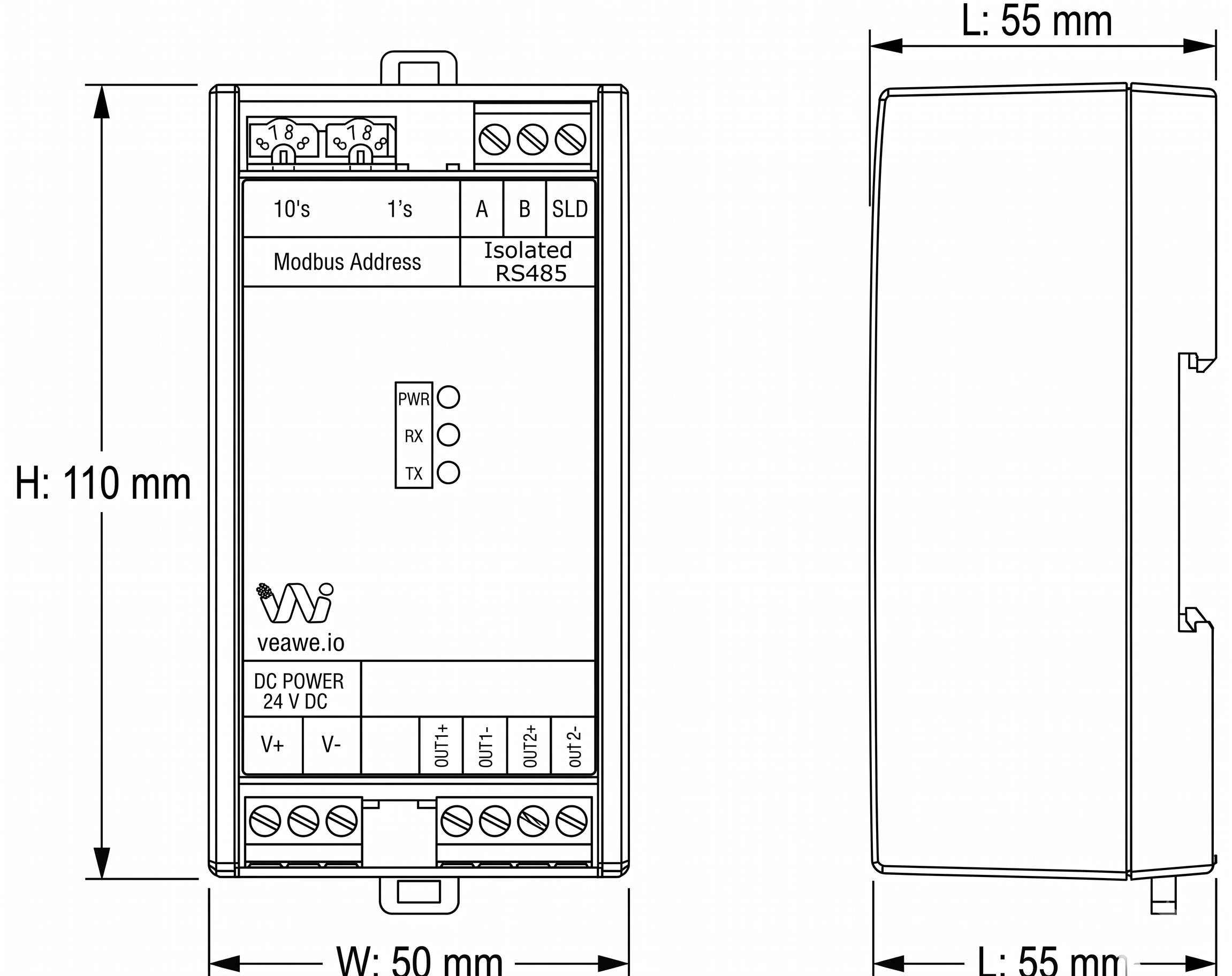
- Dimensions: 110 mm × 50 mm × 55 mm
Ordering Information
| Product Code | Description |
|---|---|
| UC-ISO-485-485 | Isolated RS485 To RS485 Repeater (2.5kVrms Isolation, 9~24V DC) |
| SPD-RS485 | Surge Protection Device RS485 |
| UC-ISO-232-485 | Isolated RS232 To RS485 Converter |
| UC-RS485-RS485 | Non-Isolated RS485 to RS485 Repeater |
| UC-ETH-RS485-D | Ethernet to Dual RS485 Converter |
Applications
- Ground Loop Elimination: Isolates RS485 nodes across different buildings, substations, or large facilities having differing ground potentials.
- Bus Distance Extension: Regenerates degraded RS485 differential signals for cable runs exceeding 1,200 meters.
- Node Capacity Multiplication: Splits overloaded RS485 networks into isolated segments of up to 256 devices each.
- VFD & Heavy Motor Noise Isolation: Protects central PLC communication lines from severe common-mode inverter noise.
Specifications
| Parameter | Value |
|---|---|
| Mounting Type | 35 mm DIN Rail Mounting |
| Dimensions | 110 mm x 50 mm x 55 mm (L x W x H) |
| Enclosure Material | Industrial ABS Plastic |
| Operating Temperature | 0 °C to +85 °C |
| Storage Temperature | -40 °C to +85 °C |
| Relative Humidity | 5% to 95% RH (non-condensing) |
Electrical Specifications
| Parameter | Specification |
|---|---|
| Power Supply | 9V ~ 24V DC (nominal 24V DC) |
| Working Current | 200 mA Max |
| Baud Rate Range | 300 bps to 250 kbps |
| Data Format | 7/8 Data bits, 1/2 Stop bits, None/Even/Odd Parity |
| RS485 Bus Receivers | Up to 256 nodes per segment |
| RS485 Receiver Input | \(\pm 12\text{V}\) between A and B max |
| RS485 Input Transmit Output | Line A weak pull-up (+5V), Line B weak pull-down (0V) |
| RS485 Input Termination | No internal termination resistor (prevents mid-bus loading) |
| RS485 Output Transmit Output | Line A pulled up (+5V), Line B pulled down (0V) |
| RS485 Output Termination | 120 \(\Omega\) termination resistor built-in across A and B |
Isolation & Protection Specifications
| Parameter | Value | Standard / Notes |
|---|---|---|
| Galvanic Signal Isolation | 2,500 V RMS | Optical/digital galvanic barrier between Input and Output ports |
| Power Isolation | 1,000 V RMS | Galvanic DC-DC isolated power supply |
| Reverse Polarity Protection | Integrated | Series diode on DC power input |
| ESD Immunity | \(\pm 15\text{kV}\) Air / \(\pm 8\text{kV}\) Contact | IEC 61000-4-2 Air Discharge and Contact Discharge |
| Surge Clamping | 600W TVS | High-speed transient suppression diodes on all lines |
LED Indications and Diagnostics
| LED | Color | Status | Description |
|---|---|---|---|
| PWR | Red | ON | Module is powered and operational |
| TX | Red | Blinking | Transmitting data out to downstream bus |
| RX | Green | Blinking | Receiving data from upstream bus |
Mechanical Dimensions
Terminal Details & Port Pinouts
Top Terminal Block (RS485-In / Host Bus)
| Terminal | Label | Function / Description |
|---|---|---|
| A | A | RS485-1 Non-inverting differential data line |
| B | B | RS485-1 Inverting differential data line |
| SLD | SLD | Cable Shield / Ground drain terminal |
Bottom Terminal Block (Power & RS485-Out / Field Bus)
| Terminal | Label | Function / Description |
|---|---|---|
| V+ | DC 24V+ | Power Supply Positive (+9V to +24V DC) |
| V- | DC GND | Power Supply Negative (Ground return) |
| A | A | RS485-2 Non-inverting differential data line |
| B | B | RS485-2 Inverting differential data line |
| SLD | SLD | Cable Shield / Ground drain terminal |
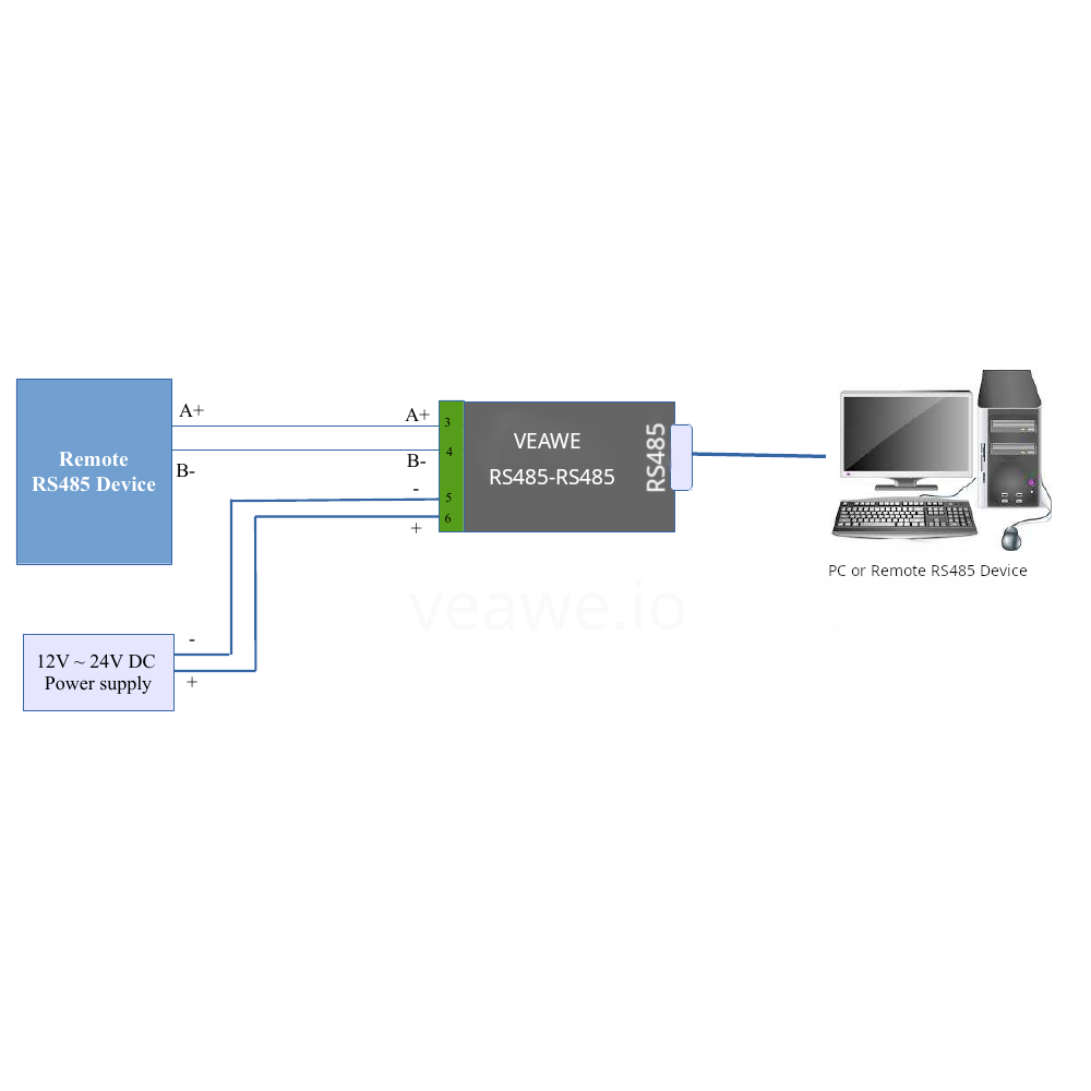
Typical Connection Diagram
Revision History
| Revision | Date | Description of Change |
|---|---|---|
| Rev 1.0 | 2026-09-09 | Initial datasheet release |
Get the latest version of this datasheet : click here..
Support
Website: www.veawe.io
Email: info@veawe.io