Loadcell Amplifier - 0-10V
Load Cell Amplifier 0–10V AC-LD-10

The AC-LD-10 (UC-LD-10V) is an industrial strain gauge load cell signal conditioner designed to convert low-level millivolt bridge signals into a clean, calibrated 0–10V DC analog output. Compatible with all standard full-bridge strain gauge load cells and force sensors, it integrates a precision sensor excitation supply, front-panel multi-turn Zero and Span adjustment potentiometers, and an ultra-fast response time of less than 1 ms. It enables seamless integration of weighing systems into PLCs, DCS controllers, and SCADA data acquisition modules.
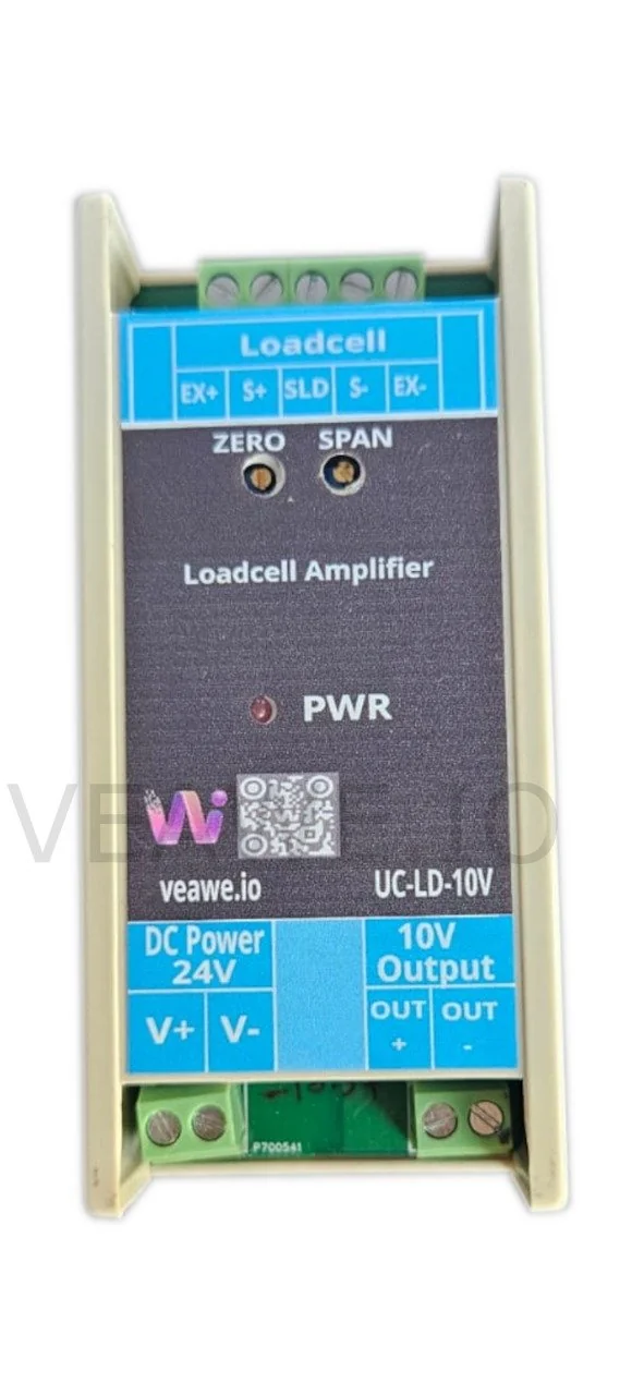
Key Features
- Full-bridge strain gauge load cell input (1 mV/V, 2 mV/V, 3 mV/V)
- Built-in precision regulated bridge excitation supply
- 0–10V DC calibrated linear analog output (< 0.5% ripple noise)
- Ultra-fast response time (< 1 ms) for dynamic weighing applications
- Front-panel multi-turn Zero and Span calibration potentiometers
- Continuous output short-circuit and input reverse polarity protection
- ±15 kV ESD protection across all signal and power terminals
- 24V DC industrial power supply input (18V to 30V DC)
- 35 mm DIN rail and wall mountable housing
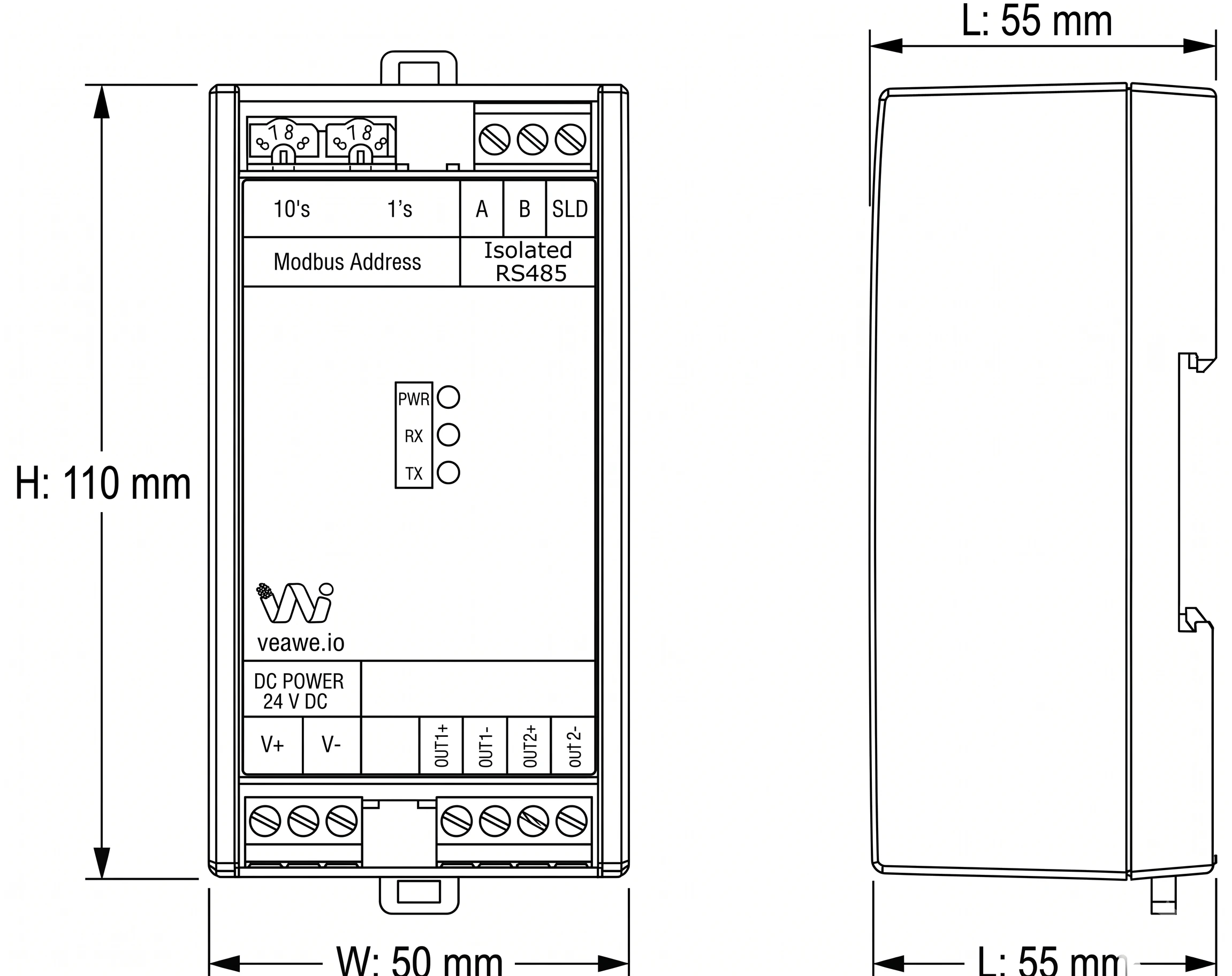
- Dimensions: 110 mm × 50 mm × 55 mm
Ordering Information
| Product Code | Description |
|---|---|
| AC-LD-10 | Load Cell Amplifier 0–10V (24V DC, DIN Rail / Wall Mount) |
| AC-LD-20mA | Load Cell Amplifier 4–20mA / 0–20mA (1.1k \(\Omega\) Load, 24V DC) |
| AC-LD-B10 | Bipolar Load Cell Amplifier ±10V (Bidirectional Tension/Compression) |
| MIO-1LD | Loadcell to Modbus RTU RS485 Transmitter |
| USS10V24V-D | Voltage Source Simulator 0-10V with Display |
| SPD-24V-DC | Surge Protection Device 24V DC |
Applications
- Silo, Tank & Hopper Weighing: Amplifying weight sensor signals for continuous vessel inventory monitoring.
- Dynamic Checkweighers & Sorting Conveyors: Sub-millisecond response enables high-throughput in-line weighing.
- Platform & Bench Scales: Interfacing industrial weighing platforms directly to automation controllers.
- Tensile & Compression Testing: Converting strain gauge load cells into standard 0–10V signals for material testing machines.
- Web Tension & Roll Measurement: Monitoring continuous roller tension in paper, textile, and converting operations.
Specifications
| Parameter | Value |
|---|---|
| Mounting Type | 35 mm DIN Rail & Wall Mounting |
| Dimensions | 110 mm x 50 mm x 55 mm (L x W x H) |
| Weight | 100 g |
| Enclosure Material | Industrial Grade ABS |
| Operating Temperature | 0 °C to +85 °C |
| Storage Temperature | -40 °C to +85 °C |
| Relative Humidity | 5% to 95% RH (non-condensing) |
Electrical Specifications
| Parameter | Specification |
|---|---|
| Power Supply Voltage | 24V DC |
| Operating Current | 200 mA @ 24V DC |
| Sensor Input Type | Full-bridge strain gauge load cell with excitation source |
| Sensor Excitation Output | Integrated precision excitation supply (EX+, EX-) |
| Output Signal Range | 0.00 V to 10.00 V DC |
| Accuracy | < \(\pm 1\%\) of Full Scale @ 25 °C ambient temperature |
| Output Ripple Noise | < 0.5% of Full Scale |
| Response Time | < 1 ms (< 1 milliSec) |
| Output Short Circuit Protection | 20 mA @ 10V continuous limiting |
| Reverse Polarity Protection | Integrated diode on 24V DC input |
| ESD Protection | \(\pm 15\text{kV}\) Air / HBM, Contact discharge across all I/O pins |
Calibration Procedure
The front-panel multi-turn trimpots allow precision field calibration:
- Zero Offset Calibration:
- Install the load cell sensor in its mechanical mounting with no external load applied (tare state).
- Measure the output voltage between terminals
OUT +andOUT -using a calibrated digital multimeter. - Adjust the front ZERO potentiometer until the output reads \(\approx 0.00\text{ V}\).
- Span Calibration:
- Place a known certified calibration test weight (or apply full-scale reference force) onto the load cell.
- Measure the output voltage and adjust the front SPAN potentiometer until the output reads \(\approx 10.00\text{ V}\) (or proportional to the applied test load).
- Verification:
- Remove the test weight and verify the output returns cleanly to \(0.00\text{ V}\). Repeat fine adjustment if required.
Mechanical Dimensions
Terminal Details & Port Pinouts
Loadcell Sensor & Power Connections
| Terminal Block | Pin | Label | Signal | Description |
|---|---|---|---|---|
| Loadcell Terminal | 1 | EX+ | Excitation (+) | Precision positive excitation voltage to load cell |
| (Top 5-Pin Block) | 2 | S+ | Signal (+) | Positive differential signal input from load cell |
| 3 | SLD | Shield | Cable shield connection (Earth ground) | |
| 4 | S- | Signal (-) | Negative differential signal input from load cell | |
| 5 | EX- | Excitation (-) | Negative excitation return to load cell | |
| DC Power | 1 | V+ | Power Input | +24V DC Operating Power Supply |
| (Bottom Left) | 2 | V- | Power Ground | 0V Power Ground Return |
| 10V Output | 1 | OUT + | Voltage Out (+) | Calibrated 0–10V DC Analog Output |
| (Bottom Right) | 2 | OUT - | Voltage Out (-) | Analog Signal Ground Return |
LED Indications and Diagnostics
| LED | Color | Status | Description |
|---|---|---|---|
| PWR | Green | ON | Operating power connected and bridge excitation active |
Revision History
| Revision | Date | Description of Change |
|---|---|---|
| Rev 1.0 | 2026-09-09 | Initial datasheet release |
Get the latest version of this datasheet : click here..
Support
Website: www.veawe.io
Email: info@veawe.io