Ethernet to Dual RS485 Converter UC-ETH...
Ethernet to Dual RS485 Converter UC-ETH-RS485-D

The UC-ETH-RS485-D is a dual-port industrial Ethernet to RS485 device server and Modbus gateway. Featuring two independently configurable RS485 serial communication channels and an auto-sensing 10/100M RJ45 Ethernet port, it integrates serial field devices into IP networks. It supports transparent data routing, multi-client TCP/UDP socket modes, and bi-directional Modbus TCP to Modbus RTU protocol conversion.
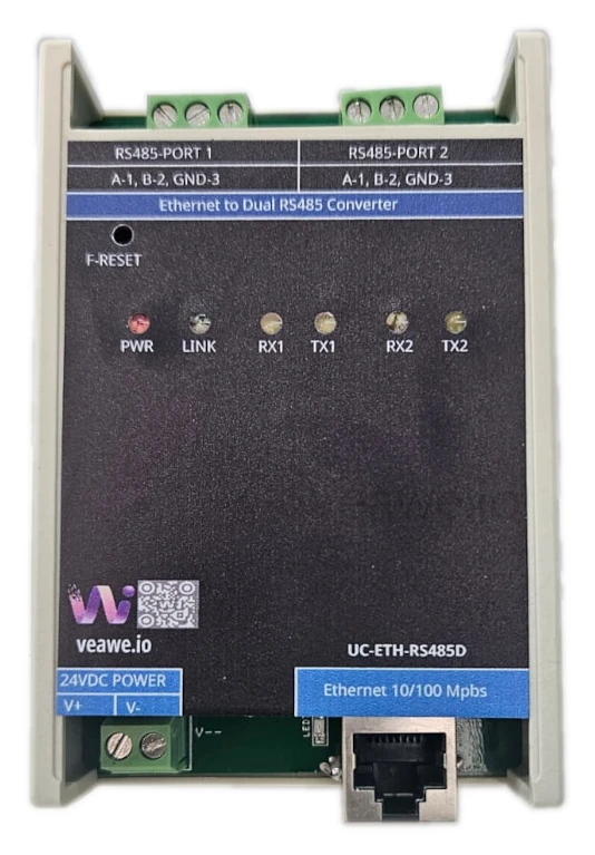
Key Features
- 2 independent RS-485 serial ports with isolated screw terminals
- Auto-sensing 10/100M Ethernet RJ45 port with 2 kV magnetic isolation
- Bi-directional Modbus TCP to Modbus RTU protocol gateway on both ports
- Multi-client TCP Server, TCP Client, UDP, and Httpd socket modes
- Transparent data pass-through for ASCII and proprietary protocols
- Built-in web server for browser-based network configuration
- Configurable baud rates from 300 bps to 250 kbps per channel
- Up to 256 nodes per RS-485 segment with built-in 120 Ω termination
- ±15 kV ESD and TVS surge protection across Ethernet, serial, and power lines
- 12V to 24V DC wide supply voltage with reverse polarity protection
- 35 mm DIN rail and wall mountable housing
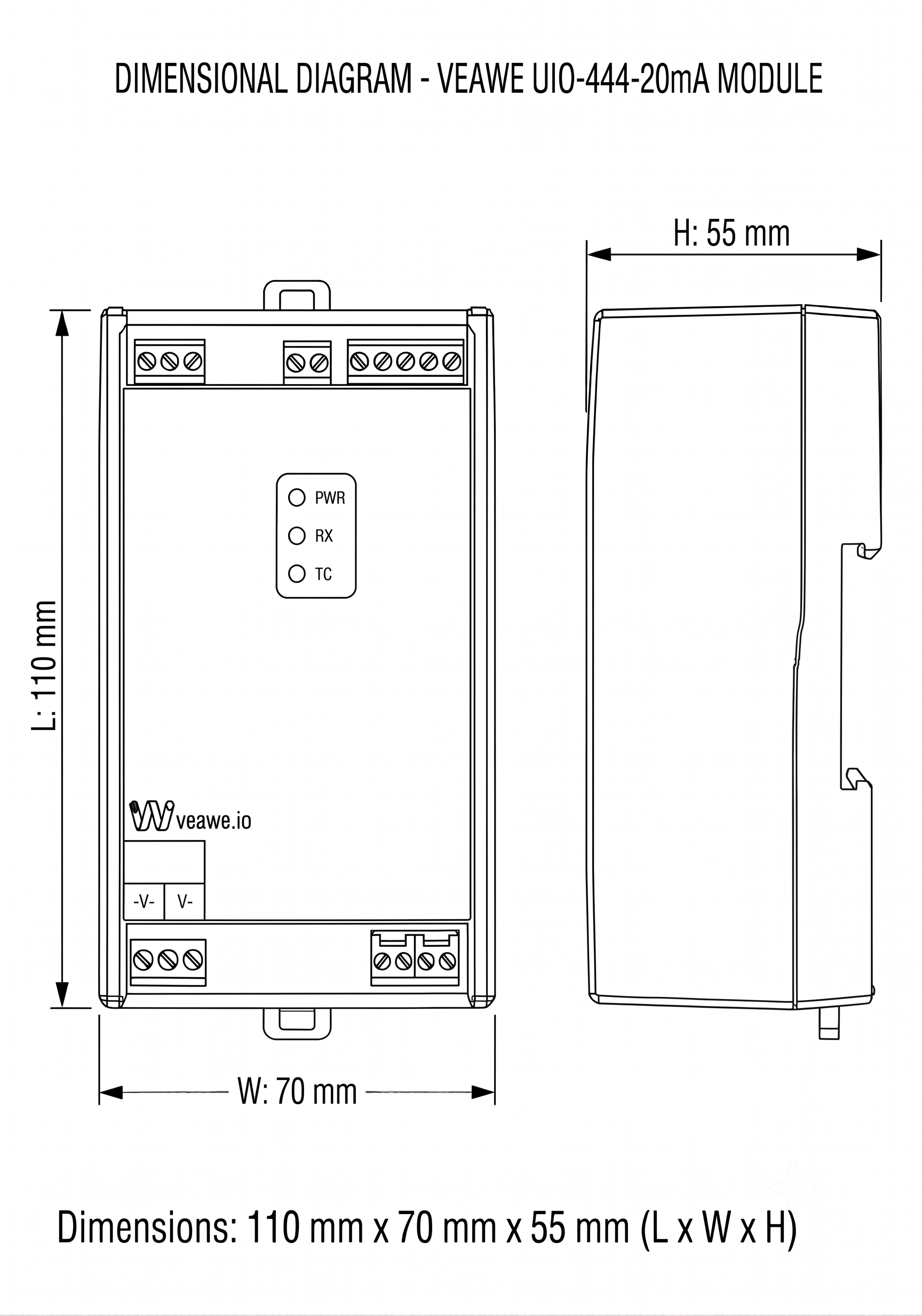
- Dimensions: 110 mm × 70 mm × 50 mm
Ordering Information
| Product Code | Description |
|---|---|
| UC-ETH-RS485-D | Ethernet to Dual RS485 Converter (Modbus TCP/RTU Gateway, 12~24V DC) |
| SPD-ETH-RJ45 | Ethernet Surge Protection Device |
| SPD-RS485 | Surge Protection Device RS485 |
| UC-ETH-RS485 | Ethernet to Single RS485 Converter |
| UC-ETH-RS232-D | Ethernet Dual RS232 Converter |
Applications
- Modbus TCP to RTU Bridging: Interfacing PLC Ethernet networks to legacy Modbus RTU energy meters, VFD drives, and I/O modules.
- Factory Automation & SCADA: Consolidating multiple distributed RS485 field loops onto high-speed plant-wide LAN backbones.
- Virtual COM Port Extension: Accessing remote serial instruments from centralized control room software without changing legacy software drivers.
- Smart Building & Energy Management: Centralizing power meters, HVAC controllers, and solar string monitoring.
Specifications
| Parameter | Value |
|---|---|
| Mounting Type | 35 mm DIN Rail & Wall Mounting |
| Dimensions | 110 mm x 70 mm x 50 mm (L x W x H) |
| Enclosure Material | Industrial ABS Plastic |
| Operating Temperature | -40 °C to +85 °C |
| Storage Temperature | -40 °C to +85 °C |
| Relative Humidity | 5% to 95% RH (non-condensing) |
Electrical Specifications
| Parameter | Specification |
|---|---|
| Power Supply | 12V ~ 24V DC (30V DC maximum limit) |
| Working Current | 200 mA Max |
| Reverse Polarity Protection | Integrated series diode on DC power input |
| Ethernet Port | 1x RJ45 10/100 Mbps auto-negotiation, auto MDI/MDIX |
| Ethernet Isolation | 2,000 V RMS built-in transformer magnetic isolation |
| Serial Ports | 2x Independent RS485 Channels (Screw Terminal blocks) |
| Baud Rate Range | 300 bps to 250 kbps |
| Data Format | 7/8 Data bits, 1/2 Stop bits, None/Even/Odd Parity |
| RS485 Receive Input | \(\pm 12\text{V}\) between A and B max |
| RS485 Transmit Output | A pulled up to +5V, B pulled down to 0V |
| RS485 Termination | 120 \(\Omega\) termination built-in on both channels |
| Max Receivers | Up to 256 transceiver nodes per channel |
Isolation & Protection Specifications
| Parameter | Value | Standard / Notes |
|---|---|---|
| Ethernet Isolation | 2,000 V RMS | Galvanic magnetic barrier across RJ45 |
| RS485 ESD Immunity | \(\pm 15\text{kV}\) Air / HBM, \(\pm 8\text{kV}\) Contact | IEC 61000-4-2 ESD protection across all RS485 lines |
| Surge Protection | Fast Transient Clamping | TVS protection across Ethernet, RS485, and power lines |
LED Indications and Diagnostics
| LED | Color | Status | Description |
|---|---|---|---|
| PWR | Red | ON | Operating power connected and regulated |
| LINK | Green | ON / Blinking | Ethernet physical link established / network activity |
| RX1 | Yellow | Blinking | Data receiving from RS485 Channel 1 bus |
| TX1 | Green | Blinking | Data transmitting onto RS485 Channel 1 bus |
| RX2 | Yellow | Blinking | Data receiving from RS485 Channel 2 bus |
| TX2 | Green | Blinking | Data transmitting onto RS485 Channel 2 bus |
| F-RESET | – | Push Button | Restores factory default network & serial parameters |
Network & Gateway Configuration
Default Factory Settings
| Parameter | Default Value | Notes |
|---|---|---|
| IP Address | 192.168.0.7 |
Static IP (DHCP selectable in web interface) |
| Subnet Mask | 255.255.255.0 |
Class C Subnet |
| Default Gateway | 192.168.0.1 |
Default router IP |
| Web UI Port | 80 |
HTTP browser access (http://192.168.0.7) |
| Web Username / Password | admin / admin |
Default credentials |
| Channel 1 TCP Port | 23 |
Default socket port for RS485-1 |
| Channel 2 TCP Port | 26 |
Default socket port for RS485-2 |
| Default Serial Settings | 115200 bps, 8, N, 1 |
Configurable 300 bps to 250 kbps |
Operating Modes & Features
- Modbus TCP to Modbus RTU Mode: Under RS485 Settings, select the operation mode to Modbus TCP to Modbus RTU. The converter transparently handles Modbus frame wrapping, checksum calculation, and transaction identification between TCP clients and RTU slaves on both channels.
- Transparent Serial Connection: Set Work Mode to
Nonefor raw serial data pass-through over TCP/UDP. Suitable for custom protocols, ASCII terminals, Virtual COM ports, and Telnet server connections. - Packet Transmission Mechanisms:
- Auto Mode (
0/0): Automatically transmits packet after 4 byte-times of silence (~350 \(\mu\)s @ 115200 Baud) or when buffer reaches 1,460 bytes. Recommended for Modbus RTU and most protocols. - Fixed Packet Mode: User-defined packet timeout (in milliseconds) and packet length (in bytes).
- Web to Serial Testing: Built-in browser tool allowing technicians to send and receive test ASCII or Hex data directly over the web UI.
Mechanical Dimensions
Terminal Details & Port Pinouts
RS485 & Power Screw Terminal Blocks
| Terminal Block | Pin | Label | Description |
|---|---|---|---|
| RS485-PORT 1 | 1 | A-1 | Channel 1 Non-inverting RS485 data signal (+) |
| (Top Left) | 2 | B-2 | Channel 1 Inverting RS485 data signal (-) |
| 3 | GND-3 | Channel 1 Signal Ground reference | |
| RS485-PORT 2 | 1 | A-1 | Channel 2 Non-inverting RS485 data signal (+) |
| (Top Right) | 2 | B-2 | Channel 2 Inverting RS485 data signal (-) |
| 3 | GND-3 | Channel 2 Signal Ground reference | |
| 24VDC POWER | 1 | V+ | Power Supply Positive (+12V to +24V DC) |
| (Bottom Left) | 2 | V- | Power Supply Negative (Ground return) |
| Ethernet | – | RJ45 | 10/100M auto-sensing Ethernet jack (2 kV magnetic isolation) |
[!WARNING] Connecting external power supply terminals to RS485 signal terminals will damage the device permanently. Always verify wiring before applying power.
Revision History
| Revision | Date | Description of Change |
|---|---|---|
| Rev 1.0 | 2026-09-09 | Initial datasheet release |
Get the latest version of this datasheet : click here..
Support
Website: www.veawe.io
Email: info@veawe.io