Isolated RS232 To RS485
Isolated RS232 to RS485 Converter UC-ISO-232-485

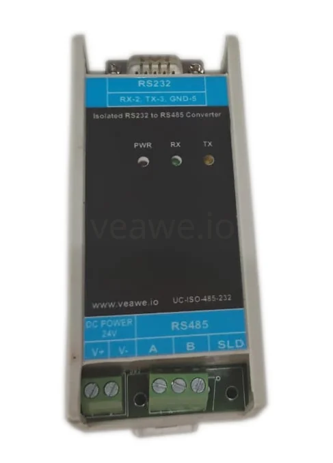
The UC-ISO-232-485 is an industrial-grade isolated RS232 to RS485 converter designed to interface legacy RS232 host equipment (PCs, PLCs, RTUs, and SCADA controllers) with robust multi-drop RS485 field networks. Featuring 2.5 kVrms signal isolation and 1 kVrms power isolation, it reliably protects host devices from heavy electrical surges, common-mode ground loops, and severe industrial EMI.
Key Features
- 2.5 kV RMS galvanic signal isolation and 1.0 kV RMS power isolation
- Converts RS-232 signals to multi-drop RS-485 differential lines
- Hardware automatic send data direction control with zero latency
- Wide supported baud rates from 300 bps to 250 kbps
- Drives up to 256 transceiver nodes on the RS-485 bus
- ±15 kV ESD and TVS surge protection on all communication ports
- Independent LED indicators for Power, TX, and RX
- 9V to 30V DC industrial power supply input (nominal 24V DC)
- 35 mm DIN rail and wall mountable housing
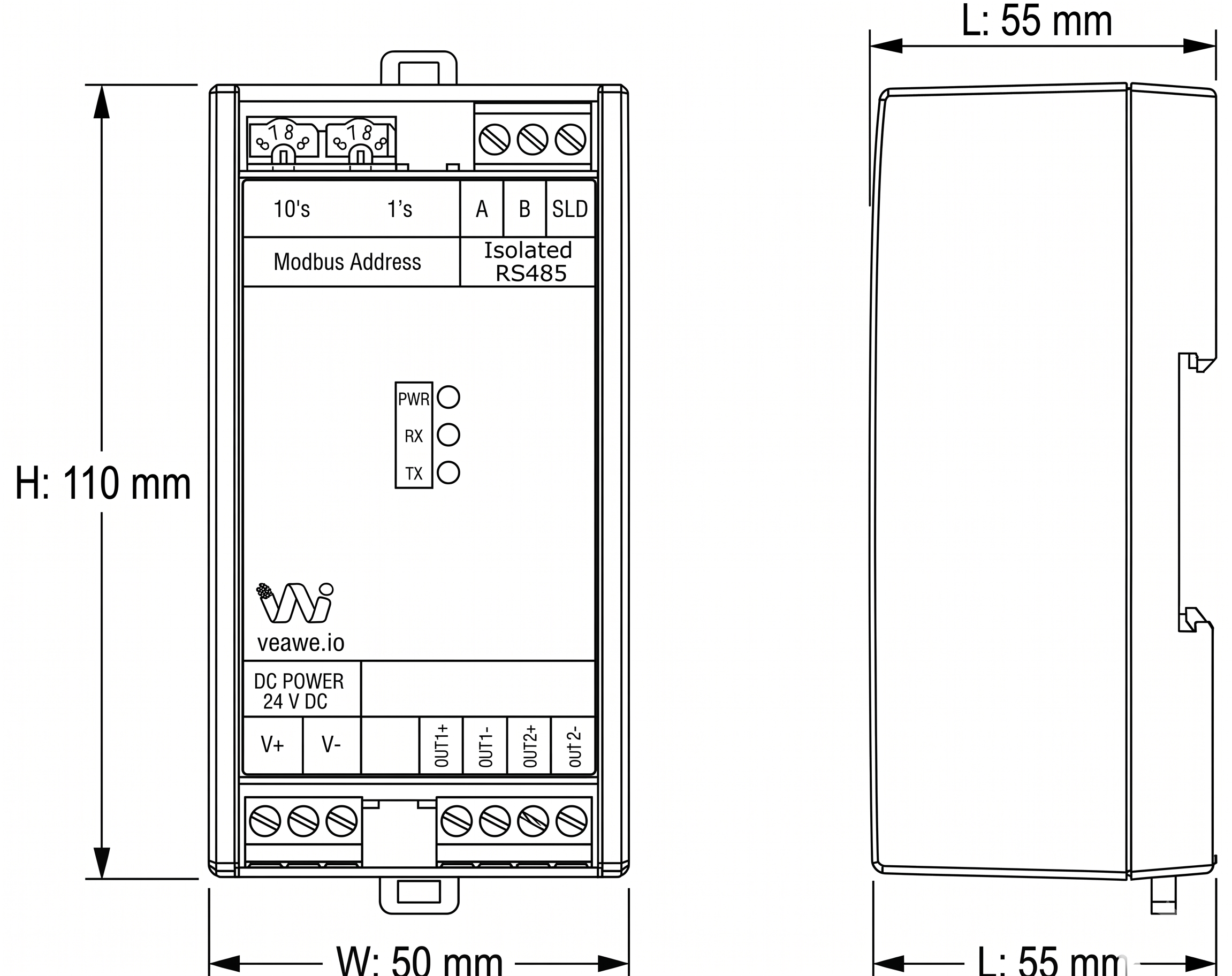
- Dimensions: 110 mm × 50 mm × 55 mm
Ordering Information
| Product Code | Description |
|---|---|
| UC-ISO-232-485 | Isolated RS232 To RS485 Converter (2.5kVrms Isolation, 9~24V DC) |
| SPD-RS485 | Surge Protection Device RS485 |
| UC-RS232-RS485 | Non-Isolated RS232 to RS485 Converter |
| UC-ISO-485-485 | Isolated RS485 To RS485 Repeater |
| UC-ETH-RS485 | Ethernet to RS485 Converter |
Applications
- Industrial Automation & Process Control: Reliable signal interfacing and device connectivity across automated production lines.
- SCADA & PLC Integration: Safe communication between host control room systems and field instrumentation.
- Long-Distance RS485 Networks: Ground potential equalization and surge suppression along extended field bus cables.
- VFD, Energy Meter & Drive Interfacing: Protects computer serial ports from motor noise and ground loops.
Specifications
| Parameter | Value |
|---|---|
| Mounting Type | Standard 35 mm DIN Rail & Wall Mounting |
| Dimensions | 110 mm x 74 mm x 35 mm (L x W x H) |
| Enclosure Material | Industrial ABS Plastic |
| Operating Temperature | 0 °C to +85 °C |
| Storage Temperature | -40 °C to +85 °C |
| Relative Humidity | 5% to 95% RH (non-condensing) |
Electrical Specifications
| Parameter | Specification |
|---|---|
| Power Supply | 9V ~ 24V DC (nominal 24V DC) |
| Working Current | 200 mA Max |
| Baud Rate Range | 300 bps to 250 kbps |
| Data Format | 7/8 Data bits, 1/2 Stop bits, None/Even/Odd Parity |
| RS485 Bus Receivers | Up to 256 nodes |
| RS485 Receiver Input | \(\pm 12\text{V}\) between A and B max |
| RS485 Transmit Output | Line A pulled up to +5V, Line B pulled down to 0V |
| RS485 Termination | 120 \(\Omega\) built-in across A and B |
| RS232 Connector | DB9 Male as per RS232C standard |
Isolation & Protection Specifications
| Parameter | Value | Standard / Notes |
|---|---|---|
| Galvanic Signal Isolation | 2,500 V RMS | Optical/digital isolation barrier between RS232 and RS485 |
| Power Isolation | 1,000 V RMS | Internal DC-DC galvanic isolation |
| Reverse Polarity Protection | Integrated | Series protection diode on DC power input terminals |
| ESD Immunity | \(\pm 15\text{kV}\) Air / \(\pm 8\text{kV}\) Contact | IEC 61000-4-2 Air Discharge and Contact Discharge |
| Surge Protection | 600W TVS | TVS clamping diodes across differential communication lines |
LED Indications and Diagnostics
| LED | Color | Status | Description |
|---|---|---|---|
| PWR | Red | ON | Power supply is connected and operational |
| TX | Red | Blinking | Transmitting data onto RS485 bus |
| RX | Green | Blinking | Receiving data from RS485 bus |
Mechanical Dimensions
Terminal Details & Port Pinouts
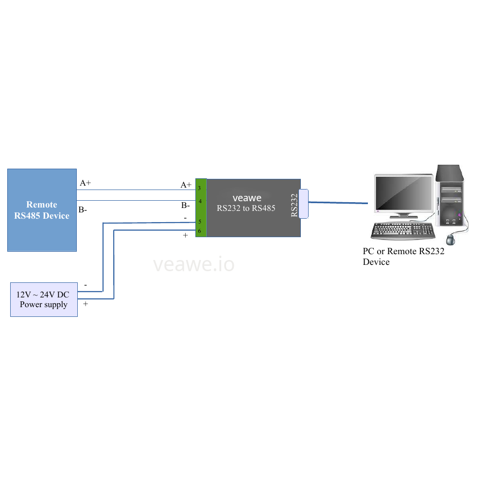
RS485 & Power Screw Terminal Block
| Terminal # | Label | Function / Description |
|---|---|---|
| 1 | A+ | RS485 Non-inverting differential data signal |
| 2 | B- | RS485 Inverting differential data signal |
| 3 | Earth / SLD | Earth ground / Cable shield drain connection |
| 4 | NC | Not Connected |
| 5 | GND | Power Supply Ground (-Vin return) |
| 6 | 24V | Power Supply Positive (+9V to +24V DC input) |
RS232 DB9 Male Connector Pinout
| DB9 Pin | Signal | Direction | Description |
|---|---|---|---|
| 2 | RX | Input | RS232 Receive data (connects to host TX) |
| 3 | TX | Output | RS232 Transmit data (connects to host RX) |
| 5 | GND | Ground | Signal Ground reference |
| 1, 4, 6, 7, 8, 9 | NC | – | No connection |
Typical Connection Diagram
Revision History
| Revision | Date | Description of Change |
|---|---|---|
| Rev 1.0 | 2026-09-09 | Initial datasheet release |
Get the latest version of this datasheet : click here..
Support
Website: www.veawe.io
Email: info@veawe.io