Isolated Analog Signal Converter Resist...

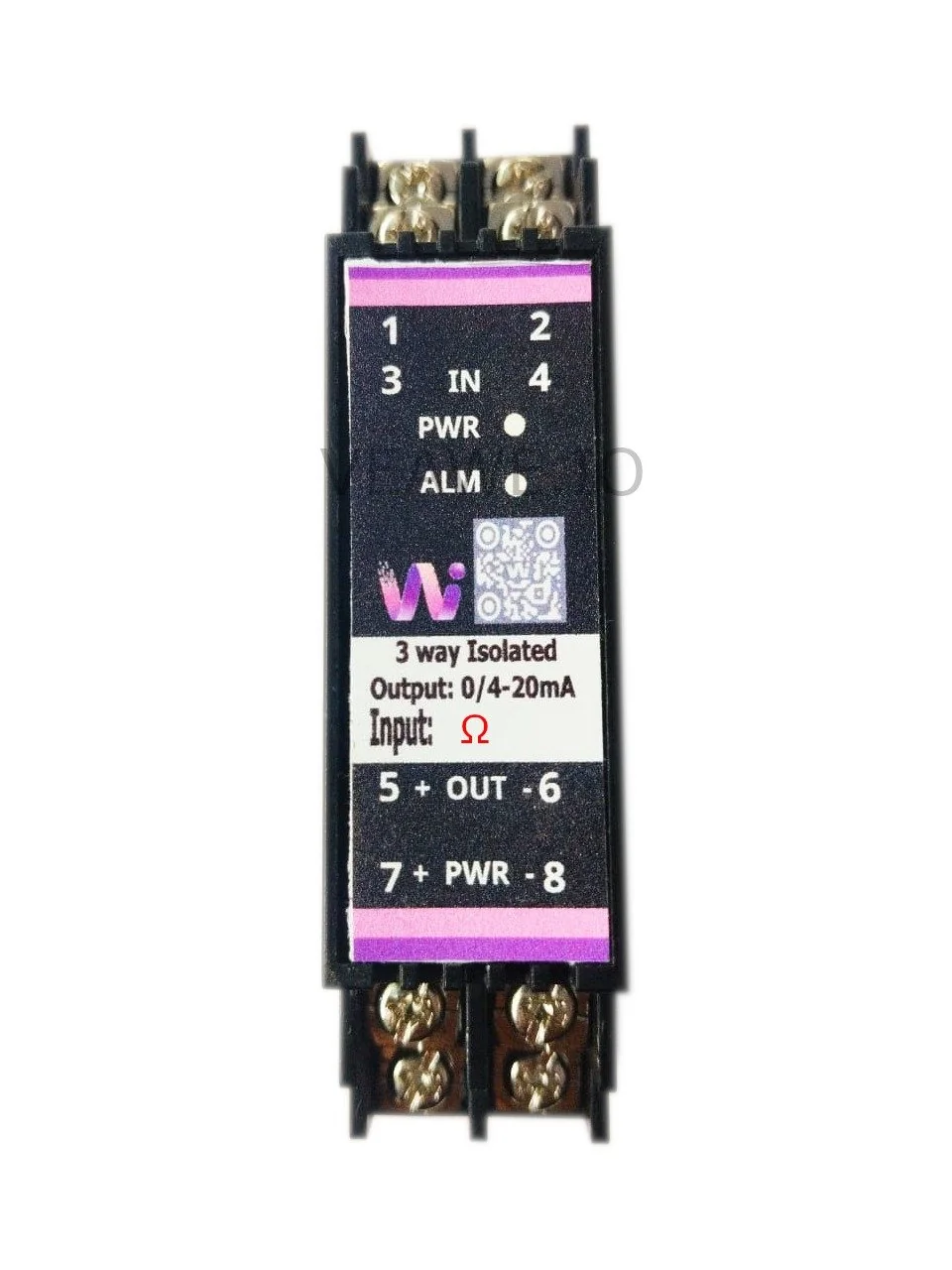
The AC-RES-420 is an industrial DIN-rail signal conditioner engineered to convert variable resistance, rheostat, and potentiometer inputs into an isolated standard analog signal (4–20mA, 0–20mA, or 0–10V DC). Supporting customizable resistance spans from 0 to 5,000 \(\Omega\) (0 to 5 k\(\Omega\)), it provides continuous linear position and resistance measurement for motorized valve positioners, float level transmitters, linear displacement transducers, and manual operator setpoint potentiometers. Engineered with 3-way galvanic isolation (1,500V AC between input, output, and power supply), it protects control electronics against destructive ground loops, line noise, and common-mode transients.
Key Features
- 3-way 1.5 kV AC galvanic isolation (input, output, and power)
- 2-wire and 3-wire potentiometer and resistance input (0 to 5,000 Ω)
- Precision linear conversion (0.2% full-scale accuracy)
- 4–20mA active current loop output driving loads up to 500 Ω
- Fast response time (≤ 10 ms) for position and level sensing
- Sensor open-circuit fault alarm indicator (
ALM) - 24V DC industrial power supply input
- Slim 25 mm DIN rail mountable housing
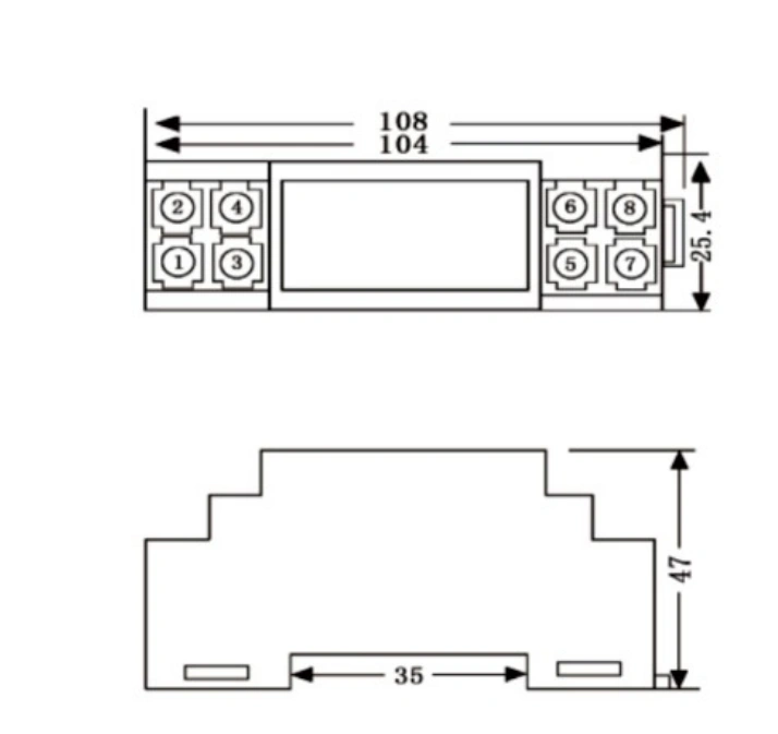
- Dimensions: 110 mm × 47 mm × 25 mm
Ordering Information
| Product Code | Description |
|---|---|
| AC-RES-420 | Isolated Resistance Signal Converter 0–5k \(\Omega\) to 4–20mA (24V DC, 3-Way Isolated) |
| AC-PT100-420 | Isolated Analog Signal Converter Pt 100 (4–20mA, 24V DC, 3-Way Isolated) |
| AC-PT1000-420 | Isolated Analog Signal Converter Pt 1000 (4–20mA, 24V DC, 3-Way Isolated) |
| AC-TCK-420 | Isolated Thermocouple Converter K-Type to 4–20mA |
| AC-TCJ-420 | Isolated Thermocouple Converter J-Type to 4–20mA |
| SPD-20MA | 4–20mA Surge Protection Device |
| USS20M24V-D | Current Source Simulator 0/4 to 20mA with Display |
Applications
- Valve Actuator Feedback: Converting potentiometer position sensors on motorized control valves into 4–20mA signals for PLC analog inputs.
- Tank Level by Float: Conditioning resistance-chain float level transmitters for continuous liquid storage level indication.
- Linear Displacement Sensing: Measuring linear slider potentiometers in hydraulic presses, injection molders, and machine tools.
- Damper & Louver Positioning: Monitoring rotary potentiometer feedback on HVAC dampers and air intake louvers.
- Manual Remote Setpoint Interfacing: Converting remote control desk potentiometers into calibrated, noise-immune 4–20mA current signals.
Specifications
| Parameter | Value |
|---|---|
| Mounting Type | 35 mm DIN Rail Mounting |
| Dimensions | 110 mm x 47 mm x 25 mm (L x H x W) |
| Weight | 100 g |
| Enclosure Material | Industrial Grade ABS |
| Operating Temperature | -20 °C to +55 °C |
| Storage Temperature | -40 °C to +85 °C |
| Relative Humidity | 5% to 95% RH (non-condensing) |
Electrical Specifications
| Parameter | Specification |
|---|---|
| Power Supply Voltage | 24V DC \(\pm 10\%\) |
| Operating Current | 100 mA @ 24V DC |
| Sensor Input Type | 2-wire / 3-wire Resistance, Potentiometer, Rheostat |
| Resistance Input Range | Customizable from 0 to 5,000 \(\Omega\) (0–5 k\(\Omega\)) |
| Measurement Accuracy | \(5\,\Omega\) (Class 0.2% of Full Scale @ 25 °C) |
| Output Signal Range | 4.00 mA to 20.00 mA (or 0–20 mA / 0–10V DC on request) |
| Maximum Output Load Resistance | \(R_L \le 500\,\Omega\) |
| Response Time | \(\le 10\text{ ms}\) (0–90% TYP) |
| Galvanic Isolation Barrier | 1,500 V AC / 1 min (3-Way: Input / Output / Power Supply) |
| Status Indicators | PWR LED (Power ON), ALM LED (Fault / Open Circuit Alarm) |
| Reverse Polarity Protection | Integrated diode on 24V DC input |
Mechanical Dimensions
Terminal Details & Wiring
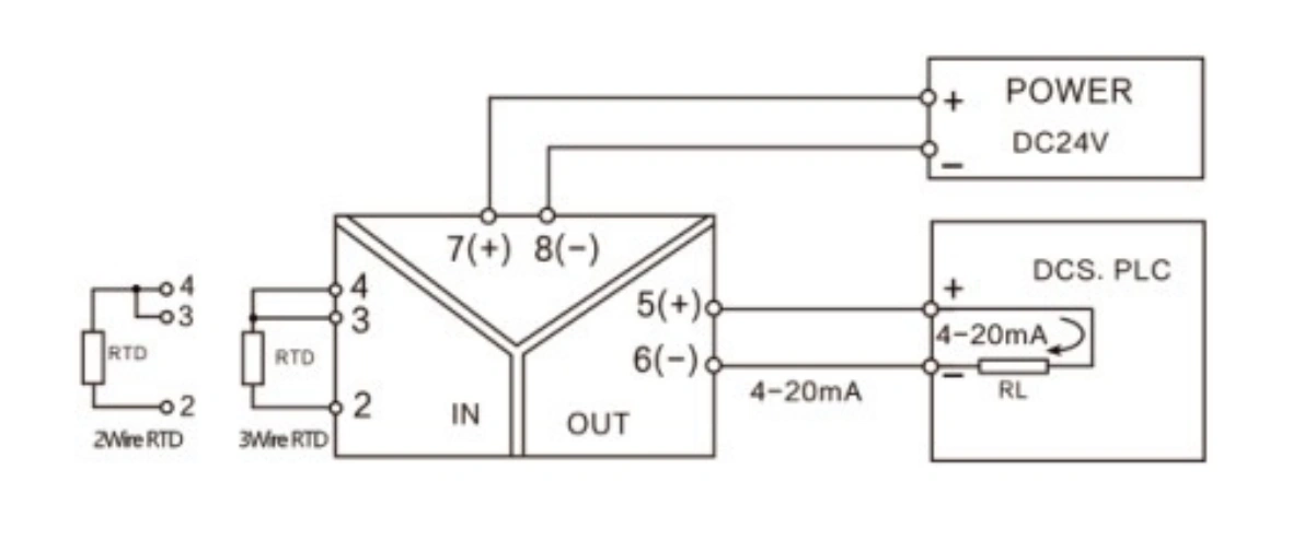
Connection Pinouts
| Terminal Block | Pin | Label | Signal | Description |
|---|---|---|---|---|
| Input Terminals | 1 | SLD | Shield | Cable shield connection (Earth ground) |
| (Top Block) | 2 | IN 2 | Return (-) | Common return / bottom end of potentiometer |
| 3 | IN 3 | Signal (+) | Wiper tap / positive sense signal | |
| 4 | IN 4 | Excitation (+) | Top end / excitation (bridge to pin 3 for 2-wire resistance) | |
| Output Terminals | 5 | OUT + | Signal Out (+) | Active 4–20mA Analog Output (+) |
| (Bottom Block) | 6 | OUT - | Signal Out (-) | Analog Signal Ground / Current Return (-) |
| Power Terminals | 7 | PWR + | 24V DC (+) | +24V DC Operating Power Supply |
| (Bottom Block) | 8 | PWR - | 0V DC (-) | Power Supply Ground Return |
Sensor Wiring Configuration
- 3-Wire Potentiometer Connection: Connect the bottom end of the potentiometer element to terminal
2, the sliding wiper contact to terminal3, and the top excitation end to terminal4. - 2-Wire Variable Resistor Connection: Connect one end of the resistor to terminal
2. Connect the other end to terminal3, and bridge terminals3and4together with a jumper wire.
LED Indications and Diagnostics
| LED | Color | Status | Description |
|---|---|---|---|
| PWR | Green | ON | Normal 24V DC operating power connected |
| ALM | Red | OFF | Normal operation; sensor input within valid range |
| ALM | Red | ON | Sensor open-circuit, broken wire, or burnout detected |
Revision History
| Revision | Date | Description of Change |
|---|---|---|
| Rev 1.0 | 2026-09-09 | Initial datasheet release |
Get the latest version of this datasheet : click here..
Support
Website: www.veawe.io
Email: info@veawe.io