Digital Environmental Sensor Modbus Module
Digital Environmental Sensor Modbus Module

Compact Modbus RTU interface module designed for digital temperature and humidity monitoring using DS18B20 and SHT40 digital sensors.
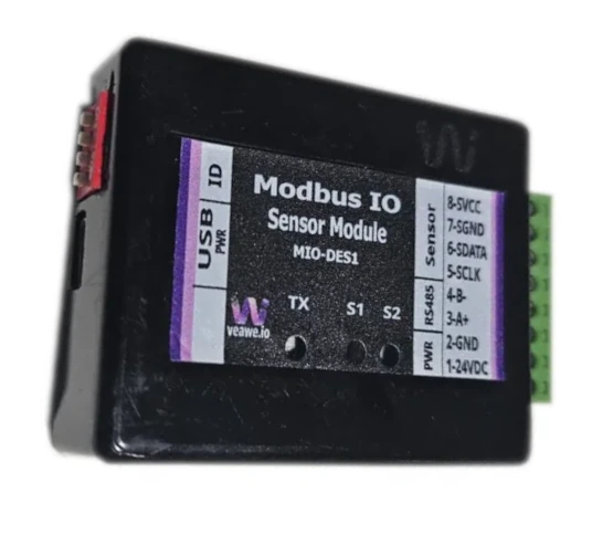
Key Features
- Multi-sensor support: Up to 4x DS18B20 digital temperature sensors or 1x SHT40 high-precision humidity & temperature sensor
- Standard Modbus RTU protocol interface over 2-wire RS-485
- Front rotary/DIP address selection switch (Addresses 1 to 15)
- Wide configurable baud rate support from 300 bps to 115200 bps
- Sensor health & open-circuit fault diagnostics with error status registers
- Dual value reporting: Scaled 16-bit integers and IEEE-754 32-bit floating point values
- Dual power input: 12~24V DC industrial field power or 5V DC USB power
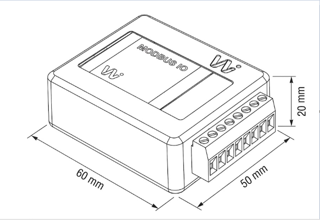
- Compact 35 mm DIN rail mounting enclosure (60 mm x 50 mm x 20 mm)
ModViz is a powerful yet simple configuration and visualization tool designed to work seamlessly with Veawe Modbus I/O modules. It enables engineers, system integrators, and technicians to quickly configure, monitor, and test field devices through an intuitive graphical interface.
The software can be downloaded from https://veawe.io/modviz/
| Product Code |
Description |
| MIO-DES1 |
Digital Environmental Sensor Interface (DS18B20 & SHT40 to Modbus RTU) |
| MIO-2AI-VI |
2-Channel Analog Input Modbus RTU RS485 Module |
| UC-RS485 |
Industrial USB to RS-485 Converter |
| SPD-RS485 |
RS-485 Communication Line Surge Protection Device |
| UC-ETH-RS485 |
Industrial Ethernet to RS-485 Modbus Gateway |
Applications
- Server Rooms & Data Centers: High-density ambient temperature and humidity tracking for rack monitoring.
- Cold Storage & Warehousing: Multi-point temperature logging across refrigerated compartments and perishable storage.
- HVAC & Building Automation: Duct and room ambient environmental monitoring integrated with BMS / SCADA.
- Industrial Process Monitoring: Enclosure and machine cabinet temperature monitoring for thermal management.
Specifications
| Parameter |
Value |
| Mounting Type |
35 mm DIN Rail Mounting |
| Dimensions |
60 mm x 50 mm x 20 mm (L x W x H) |
| Enclosure Material |
Industrial ABS plastic |
| Operating Temperature |
-20 °C to +70 °C |
| Storage Temperature |
-40 °C to +85 °C |
| Relative Humidity |
5% to 95% RH (non-condensing) |
Electrical Specifications
| Parameter |
Value |
| Supply Voltage |
12V to 24V DC (Nominal 24V DC) or USB 5V DC |
| Power Consumption |
< 0.5 W @ 24V DC |
| Communication Interface |
RS-485 (2-Wire Half-Duplex) |
| Baud Rate Range |
300, 600, 1200, 2400, 4800, 9600, 19200, 38400, 57600, 115200 bps |
| Data Format |
8 Data Bits, 1 Stop Bit, None / Even / Odd Parity |
| Parameter |
Specification |
| Supported Sensor Types |
Maxim DS18B20 (1-Wire) or Sensirion SHT40 (I2C) |
| DS18B20 Capacity |
Up to 4 independent 1-Wire temperature sensors |
| DS18B20 Temp Range |
-55 °C to +125 °C (Accuracy ±0.5 °C from -10 °C to +85 °C) |
| SHT40 Temp Range |
-40 °C to +125 °C (Accuracy ±0.2 °C) |
| SHT40 Humidity Range |
0% to 100% RH (Accuracy ±1.8% RH) |
Isolation & Protection Specifications
| Parameter |
Value |
Notes / Description |
| Supply Reverse Polarity Protection |
Integrated |
Series protection diode on DC power inputs |
| Transient Voltage Clamping |
Up to 600W |
TVS suppression diodes on power and RS-485 lines |
| RS-485 Bus ESD Protection |
±15 kV |
IEC 61000-4-2 Air Discharge / HBM |
Mechanical Dimensions
Terminal Details
| Pin |
1 |
2 |
3 |
4 |
5 |
6 |
7 |
8 |
| Signal |
24V+ |
24V- |
A+ |
B- |
VCC_S |
DQ / SDA |
SCL |
GND_S |
Wiring Diagrams
Note: All connection diagrams shown are for illustrative purposes and standard sensor connections.
Communication Interface
| Protocol |
Physical Layer |
Default Baud Rate |
Default Format |
| Modbus RTU |
RS-485 |
19200 |
8N1 |
Basic Process Registers
| Signal |
Address |
Type |
Description |
| Temp 1 / SHT40 Temp |
30001 |
int16 |
Temperature value in 0.1 °C units (e.g. 254 = 25.4 °C) |
| SHT40 Humidity |
30002 |
int16 |
Relative humidity in 0.1 %RH units (e.g. 550 = 55.0 %RH) |
Supported Modbus Function Codes
| Read |
Write |
| 02 – Read Discrete Inputs |
06 – Write Single Register |
| 04 – Read Input Registers |
16 – Write Multiple Registers |
Register Map Overview
| Function |
Address Range |
Type |
Description |
| Discrete Inputs |
10001–10004 |
Bit |
Sensor 1 to 4 connection / fault status (1 = Fault/Open) |
| Input Registers |
30001–30004 |
int16 |
Sensor 1 to 4 Temperature integer values (0.1 °C) |
| Input Registers |
30005 |
int16 |
SHT40 Humidity integer value (0.1 %RH) |
| Input Registers |
30011–30018 |
float32 |
Sensor 1 to 4 Temperature float values (IEEE-754) |
| Input Registers |
30019–30020 |
float32 |
SHT40 Humidity float value (IEEE-754) |
| Holding Registers |
40101 |
int16 |
Modbus slave address (1 to 15 from DIP switch) |
| Holding Registers |
40102 |
int16 |
Baud rate selection (0=9600, 1=19200, 2=38400, etc.) |
| Holding Registers |
40103 |
int16 |
Parity & framing configuration |
| Holding Registers |
40201 |
int16 |
Connected sensor configuration (0=DS18B20, 1=SHT40) |
Detailed Register Tables
| Address |
Description |
| 10001–10004 |
Sensor 1 to 4 open-circuit / disconnect fault flag |
| Address |
Type |
Description |
| 30001–30004 |
int16 |
Sensor 1 to 4 Temperature (scaled by 10) |
| 30005 |
int16 |
SHT40 Relative Humidity (scaled by 10) |
| 30011–30018 |
float32 |
Sensor 1 to 4 Temperature IEEE-754 float (°C) |
| 30019–30020 |
float32 |
SHT40 Relative Humidity IEEE-754 float (%RH) |
Holding Registers (4xxxx)
Communication Settings
| Address |
Type |
Description |
| 40101 |
int16 |
Slave address (read from front DIP switch) |
| 40102 |
int16 |
Baud rate code (Default: 1 = 19200 bps) |
| 40103 |
int16 |
Serial parity (0 = 8N1, 1 = 8E1, 2 = 8O1) |
Default Settings
| Parameter |
Default Value |
| Modbus Address |
Defined by DIP switch (Default: 1) |
| Baud Rate |
19200 bps |
| Parity & Framing |
8 Data bits, No Parity, 1 Stop bit (8N1) |
Configuration Settings
- Address Selection: Set via onboard DIP switch from address 1 to 15.
- Baud Rate Configuration: Configurable using ModViz software tool or writing to Holding Register 40102.
LED Indications and Diagnostics
| LED |
Color |
Status |
Description |
| PWR |
Red |
ON |
Power supply 24V DC / USB 5V normal |
| TX/RX |
Green |
Blinking |
RS-485 Modbus communication active |
| FAULT |
Yellow |
ON |
Sensor disconnected or wire open circuit |
Revision History
| Revision |
Date |
Description of Change |
| Rev 1.0 |
2026-09-09 |
Initial datasheet release for MIO-DES1 |
Get the latest version of this datasheet : click here..
Support
Website: www.veawe.io
Email: info@veawe.io